
Extreme ultraviolet light source and target for extreme ultraviolet light source

A technology of far ultraviolet region and ultraviolet light, which is applied in the field of far ultraviolet region light source and target field of far ultraviolet region light source, which can solve the problems of device precision reduction and damage to optical system, so as to reduce energy loss, improve luminous efficiency and suppress debris the effect of

Inactive Publication Date: 2006-04-12
KANSAI TLO KK
View PDF1 Cites 7 Cited by
  • Summary
  • Abstract
  • Description
  • Claims
  • Application Information

AI Technical Summary

Problems solved by technology

The flying particles (fragments) may adhere to or damage the optical system, etc., so there is a problem that the accuracy of the device is reduced.

Method used


Image

  • Extreme ultraviolet light source and target for extreme ultraviolet light source
  • Extreme ultraviolet light source and target for extreme ultraviolet light source
  • Extreme ultraviolet light source and target for extreme ultraviolet light source

Examples


Embodiment Construction

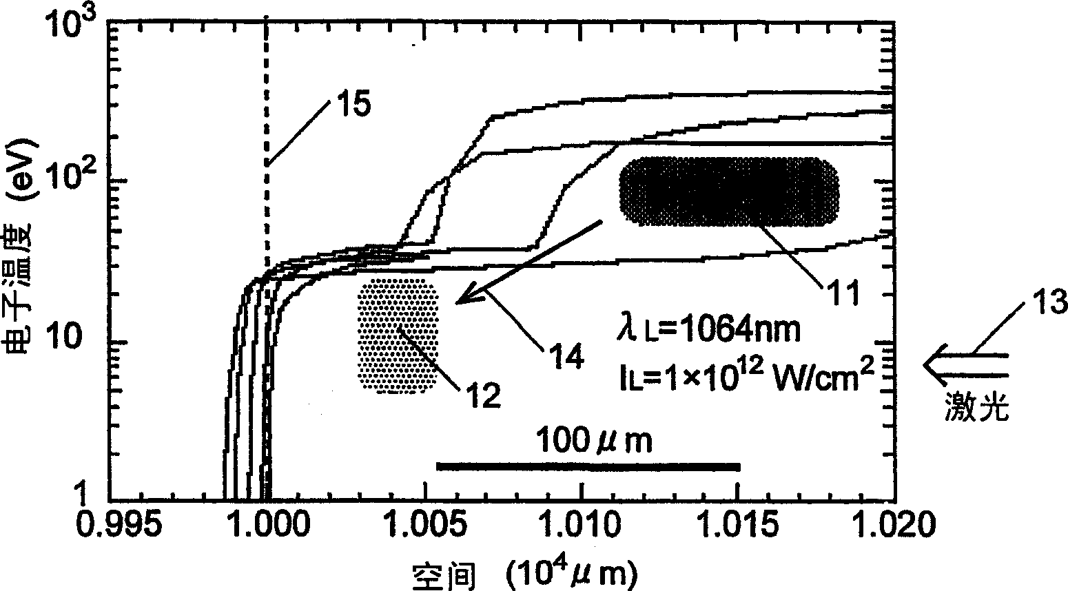
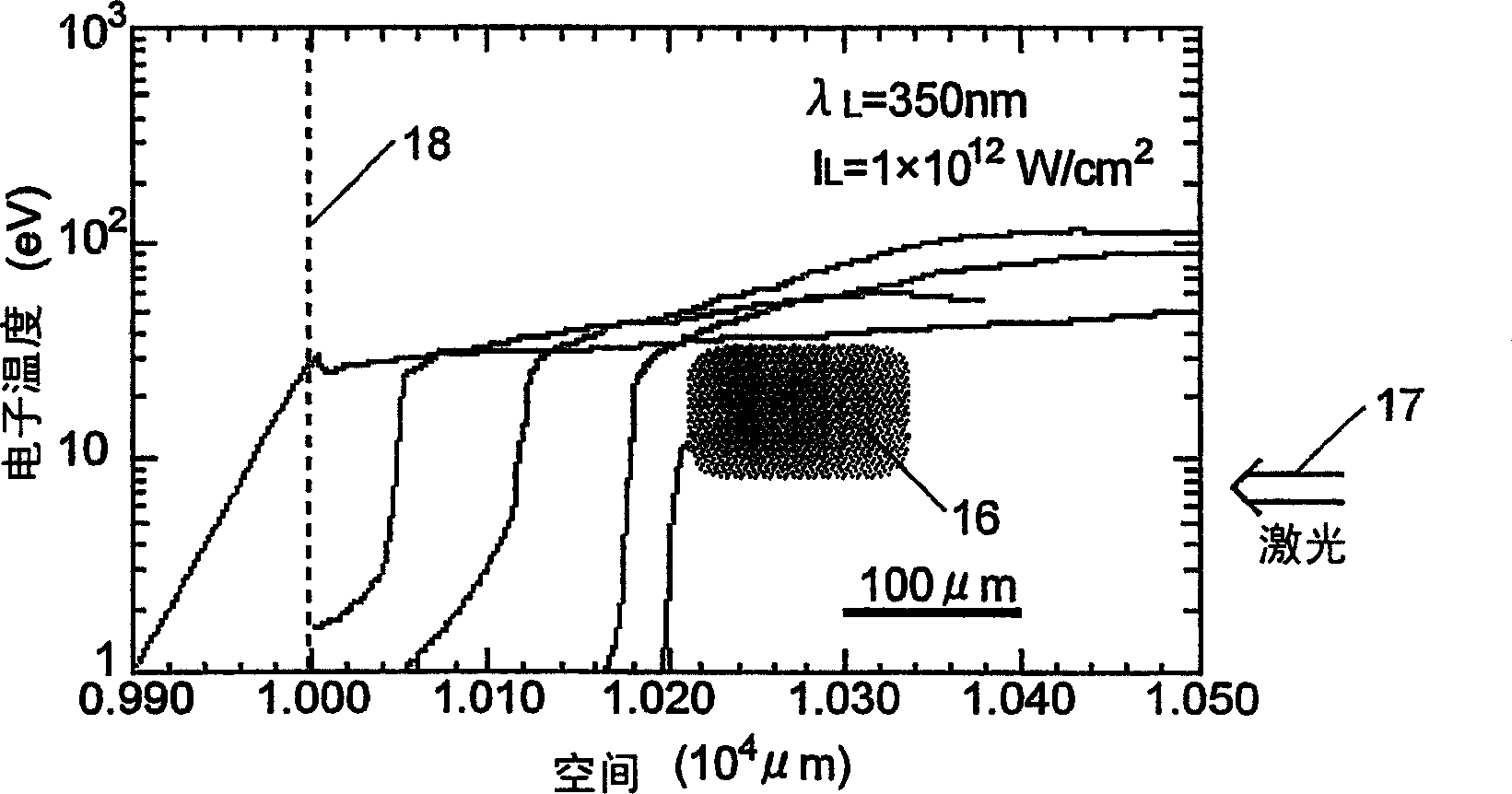
[0037] First, as an example of a target for a light source in the far ultraviolet region of the first embodiment, a target containing SnO as a heavy metal compound is described. 2 (tin dioxide) target (hereinafter referred to as "low-density SnO 2 target").

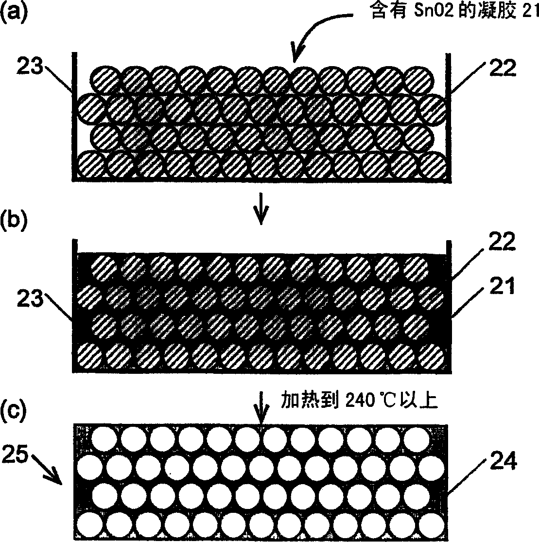
[0038] Low-density SnO that illustrates the present invention 2 The first manufacturing method of the target. First, 1.0 g of SnCl 4 (tin tetrachloride) was added to 20.0 g of dehydrated methanol (methanol not containing water as an impurity), followed by stirring. Thus, a methanol solution of tin (IV) methoxy in which the hydroxyl group of methanol was substituted with tin (IV) was obtained. 50 ml of pure water was mixed in this solution. Thus, the SnO containing SnO after tin(IV) methoxyl hydrolysis was obtained. 2 gel. After the gel was applied to a glass substrate, it was dried to obtain a thickness of 100 μm and a density of 0.05 g / cm 3 low density SnO 2 target. In addition, the density value of this target...


PUM

PropertyMeasurementUnit
wavelengthaaaaaaaaaa

Abstract

A target for extreme ultraviolet light sources for emitting an extreme ultraviolet light with high luminous efficiency. The target is solid and made of a heavy metal or the heavy metal compound with a density of 0.5 to 80% of the crystal density. If the target is irradiated with a laser beam, a plasma of the heavy metal contained in the target is produced and an extreme ultraviolet light with a predetermined wavelength corresponding to the heavy metal is emitted from the plasma. Since the density of the target is smaller than the crystal density as stated above, the spatial distribution of the plasma density can be controlled, and the region in which the plasma absorbs the energy of the laser beam can be made to agree with the region in which the plasma emits extreme ultraviolet light. Therefore, the energy loss is reduced and the luminous efficiency is improved. For example, the luminous efficiency of light with a wavelength at or near 13.5 nm generated when an SnO2 target the density of which is 24% of the crystal density is used is higher than that when an Sn crystal target is used.

Description

technical field [0001] The present invention relates to a target for generating light in the extreme ultraviolet region with a wavelength of 1 to 100 nm, a method for manufacturing the target, and a light source in the extreme ultraviolet region using the target. The target and the light source in the deep ultraviolet region are preferably applicable to lithography and the like in the manufacture of semiconductor devices. Background technique [0002] Semiconductor integrated circuits are generally fabricated using lithographic techniques. Since the minimum processing size of lithography depends on the wavelength of irradiated light, it is necessary to shorten the wavelength of irradiated light in order to increase the integration degree of integrated circuits. Specifically, lithography using light in the wavelength range of 11 nm to 14 nm among ultra-short ultraviolet light is aimed at practical use, compared to the current lithography performed by light having a wavelengt...

Claims


Application Information

Patent Timeline
Patent Type & Authority Applications(China)
IPC IPC(8): H01L21/027G03F7/20G21K1/00G21K5/02H05G1/00H05H1/24H01J35/08H05G2/00
CPCB82Y10/00G03F7/70033H05G2/001G03F7/2004
Inventor 长井圭治西村博明乘松孝好西原功修宫永宪明中塚正大井泽靖和山中龙彦中山光男重森启介村上匡且岛田义则内田成明古河裕之砂石淳瓦西利·扎克夫斯基松井亮二日比野隆宏奥野智晴
Owner KANSAI TLO KK
Learn More