Sequential batch reactor with biofilm configuration for treating complex chemical and pharmaceutical effluents
A reactor and biofilm technology, applied in the field of continuous batch reactors, can solve the problem of no chemical sewage research
- Summary
- Abstract
- Description
- Claims
- Application Information
AI Technical Summary
Problems solved by technology
Method used
Image

Examples
Embodiment 1
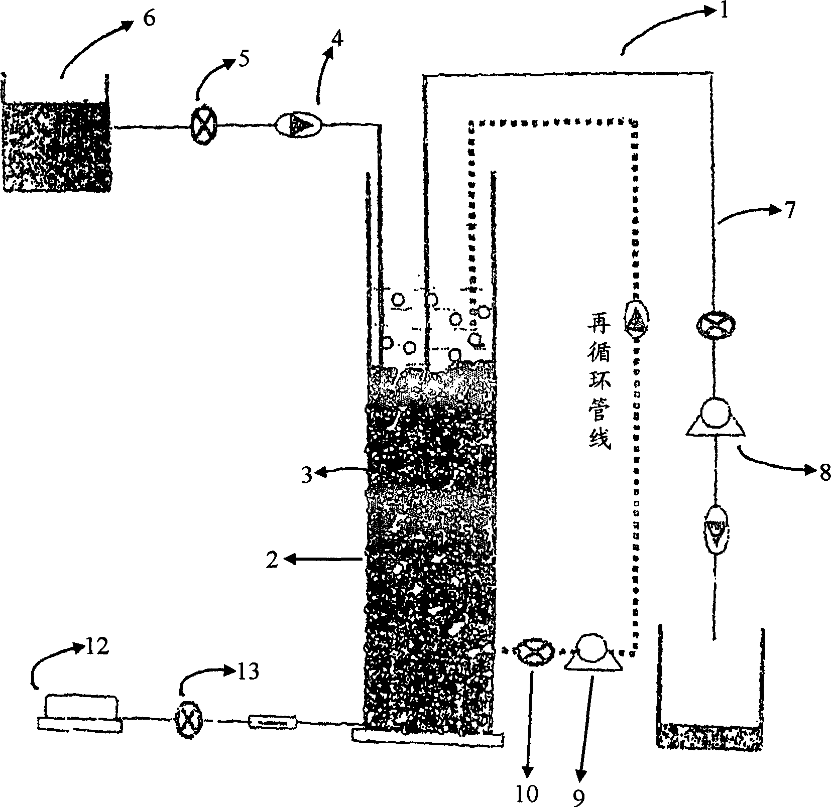
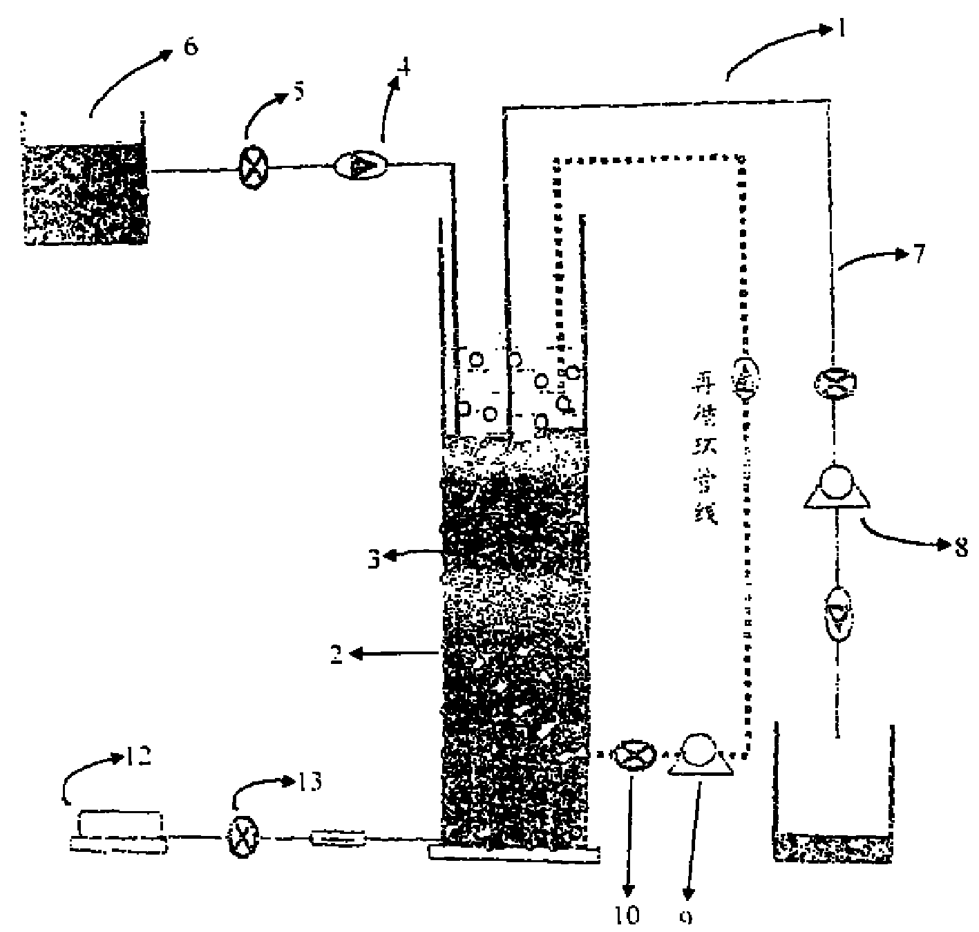
[0060] During start-up of any bioreactor, reactor start-up is one of the important aspects to consider. The SBR was inoculated with organisms obtained from an activated sludge processing (ASP) unit obtained at an operational laboratory level, which had been continuously used for the past 3 years to treat complex chemical effluents. The mixed liquor from the aerobic chamber of the ASP unit was taken and fed as inoculum to the SBR reactor at a reactor volume ratio of 1:5.
[0061] After inoculation, synthetic feed (glucose: 1 g / L; sodium acetate: 1 g / L; Na 2 HPO 4 : 0.31 g / L) to run the reactor on the fixed bed for up to 7 days to accumulate biomass (biofilm VSS: 3 g / L). Then, the reactor is fed with 0.8kg COD / m 3 The organic loading rate per day is carried out with a specified waste liquid (pH: 7-83; TDS: 11g / L, SS: 0.9g / L; oil and grease: 14mg / L; ammonia nitrogen: 35mg / L; COD: 6g / L ; BOD: 2.4g / L, chloride: 5g / L; sulfate: 1.7g / L; phosphate: 360mg / L; phenol: 7.8mg / L).
[00...
Embodiment 2
[0064]The performance of an SBR for processing complex chemical effluents was evaluated by monitoring carbon removal (COD) throughout the reactor operation and throughout the cycle. In addition, pH, BOD, sulfate, suspended solids (SS) and dissolved oxygen (DO) were also measured in sequential operations to evaluate the performance of the SBR. The analytical procedures for monitoring the above parameters follow the procedures given in Standard Methods (Stand Methods, APHA, 1996).
Embodiment 3
[0066] At 0.8kg COD / m 3 The organic loading rate per day, using a full 24-hour cycle to carry out SBR in continuous batch mode, was used in this study to evaluate the suitability of the reactor for treating the complex chemical wastewater. In the initial stage (15 days) of described reactor start-up, with 0.8kgCOD / m 3 The reactor was operated at an organic loading rate per day and the performance of the reactor was evaluated by monitoring carbon removal (COD and BOD) during the sequential (cyclic) operation as well as throughout the reactor operation .
[0067] serial number
[0068] For COD, at 0.8kg COD / m 3 A removal of 78% was observed at an organic loading rate of A 91% removal of BOD was observed after stabilization of the reactor was achieved. From the reactor performance data obtained it can be deduced that the SBR showed much better performance in terms of COD removal when compared to the existing ASP system. With different organic loading rates (0.8kg C...
PUM
 Abstract
Description
Claims
Application Information
 - R&D
- Intellectual Property
- Life Sciences
- Materials
- Tech Scout
- Unparalleled Data Quality
- Higher Quality Content
- 60% Fewer Hallucinations
Browse by: Latest US Patents, China's latest patents, Technical Efficacy Thesaurus, Application Domain, Technology Topic, Popular Technical Reports.
© 2025 PatSnap. All rights reserved.Legal|Privacy policy|Modern Slavery Act Transparency Statement|Sitemap|About US| Contact US: help@patsnap.com