

Mixed powder for powder metallurgy
A technology of mixed powder and powder metallurgy, which is applied in the field of mixed powder for powder metallurgy, and can solve the problems of insufficient improvement of the fatigue strength of sintered bodies
- Summary
- Abstract
- Description
- Claims
- Application Information
AI Technical Summary
Problems solved by technology
Method used
Image

Examples
Embodiment 1
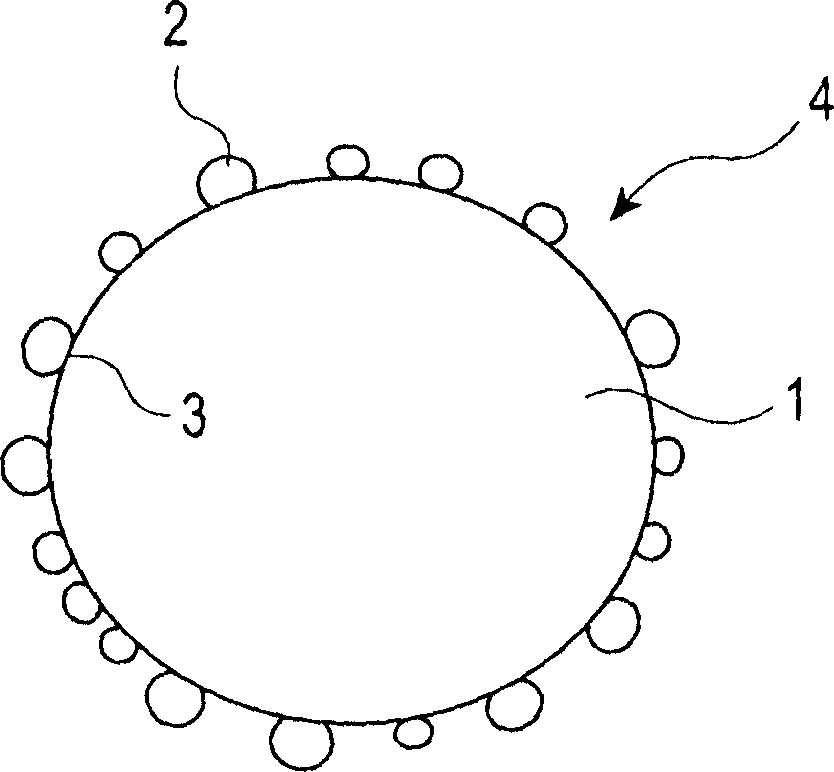
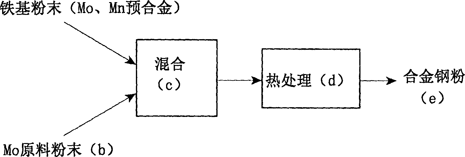
[0113] Molten steel containing predetermined amounts of Mo and Mn is sprayed by a water atomization method to form an atomized iron-based powder (average particle diameter: 70 to 90 μm). MoO with an average particle size of 1 to 3 μm is added to the iron-based powder at a predetermined ratio 3 The powder was used as Mo raw material powder, and was mixed in a V-type mixer for 15 minutes.
[0114] The mixed powder was heat-treated in a hydrogen atmosphere with a dew point of 30°C (holding temperature 875°C, holding time 1 hour), and the MoO 3 The powder is reduced to Mo metal powder, and is diffusely attached to the surface of the iron-based powder to produce alloy steel powder. In addition, the average particle size of any of the alloy steel powders was in the range of 70 to 90 μm. Add Ni powder (carbonyl Ni powder) with an average particle size of 4 μm and Cu powder (electrolytic Cu powder) with an average particle size of 20 μm on the alloy steel powder, and mix them in a V...
Embodiment 2
[0130] Using the same method as in Example 1, a predetermined amount of Mo and Mn were used as a pre-alloy, and a predetermined amount of Mo (Mo metal powder, Fe-10 mass% Mo, Fe-50 mass% Mo) was diffused and attached to the surface. alloy steel powder. In this alloy steel powder, add the Ni powder of the average particle diameter of 4 μm of predetermined amount, the graphite powder of 0.3 mass %, add the ethylenebisstearamide of 0.6 mass parts as lubricant and binding agent concurrently, heat to 160° C. and mixed for 10 minutes to make Ni powder adhere to the surface of the alloy steel powder (Samples No. 26, No. 29, and No. 30). Among them, Ni powder was mixed and added to No. 31 after the binder was added and heated and mixed, and the mixed powder was formed by the same treatment. In addition, for No. 32 and No. 33, which is a comparative example of composition, enhanced sintering (1250°C-60 minutes, N 2 -10vol%H 2 atmosphere).
[0131] Furthermore, an alloy steel powder...
Embodiment 3
[0143] In the same method as in Example 1, a predetermined amount of Mo raw material powder (MoO 3 powder). This mixed powder was heat-treated in a hydrogen atmosphere with a dew point of 30° C. at a holding temperature (900 to 1050° C.) different from Example 1, and alloy steel powders shown in Table 5 Nos. 34 to 36 were produced. In addition, the alloy steel powder Nos. 1 to 5 of Example 1 are also shown in Table 5.
[0144] The area ratio of the region where the Mo concentration is 2.0% by mass or more was measured by the following method. After embedding the alloy steel powder in the resin, it is ground, and 10 particle cross-sections (parts with a cross-sectional diameter within ±10% of the average particle diameter) are selected and analyzed by EPMA to measure the area where the Mo concentration is 2.0% by mass or more. The area was calculated by image analysis. The values (10 pieces) obtained from each cross section were averaged and made the area ratio of the regi...
PUM
| Property | Measurement | Unit |
|---|---|---|
| density | aaaaa | aaaaa |
| particle size | aaaaa | aaaaa |
Abstract
Description
Claims
Application Information