
On-board engine using compressed air as power

A compressed air and engine technology, applied to engine components, variable displacement engines, machines/engines, etc., can solve problems such as short cruising range, damage to human living environment, complicated engine structure, etc., and achieve the effect of simple structure

Inactive Publication Date: 2006-10-25
陈志新
View PDF0 Cites 42 Cited by
  • Summary
  • Abstract
  • Description
  • Claims
  • Application Information

AI Technical Summary

Problems solved by technology

[0003] Besides, the power obtained by burning fuel will cause air pollution and emission problems
No matter how complete the combustion of the machine, the combustion will also consume the oxygen in the atmosphere, produce carbon dioxide, and cause damage to the living environment of human beings; there are also harmful gases emitted, which will play an immeasurable harmful effect on the human body and the living environment of human beings.
[0004] In order to eliminate the above hazards, environmentally friendly electric vehicles have been developed, but so far, due to many problems, especially low power and short cruising range, it is still difficult to be widely used
[0005] Although modern engines have made great fuel-saving improvements, for example, an engine that burns a lean mixture has been developed, but it can only save a small amount of fuel, and a lot of auxiliary equipment has been added to reduce the performance of the engine
[0006] In order to reduce the emission of exhaust gas, people have made various attempts, including the use of three-way catalytic converters, etc., but these attempts require additional equipment and are difficult to achieve satisfactory results
[0007] Because the traditional engine is a heat engine, it needs a cooling system to cool it. Because the gasoline engine is an ignition engine, it also needs an ignition system. Therefore, the traditional engine has a complicated structure, many auxiliary parts, and high manufacturing costs.

Method used


Image

  • On-board engine using compressed air as power
  • On-board engine using compressed air as power
  • On-board engine using compressed air as power

Examples


Embodiment Construction

[0021] The present invention will be further described below in conjunction with accompanying drawing.

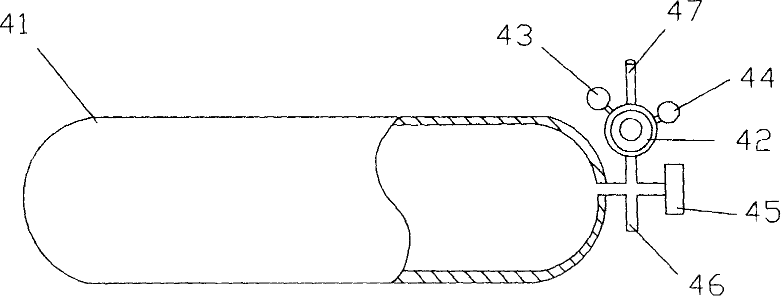
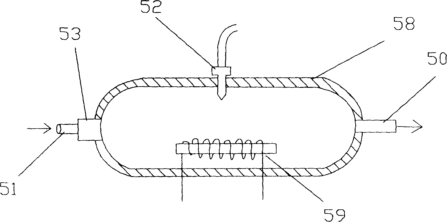
[0022] Such as figure 1 Shown is a structural schematic diagram of the energy cylinder and the pressure regulating system of the present invention. Wherein there is an energy cylinder 41, which is a cylindrical or cuboid high-pressure container made of carbon fiber. Adjust the decompressed system pressure according to the conditions (engine speed and load). 43 among the figure is the high pressure side pressure gauge. According to its reading, the residual pressure in the energy cylinder can be known. 44 among the figure is the pressure gauge after decompression. The pressure in the system after decompression can be known according to the reading. 45 in the figure is a manual open valve, which is used to artificially open the working valve that the energy cylinder communicates with the outside. 46 among the figure is the output gas pipe joint, is used for connecting h...


PUM


Abstract

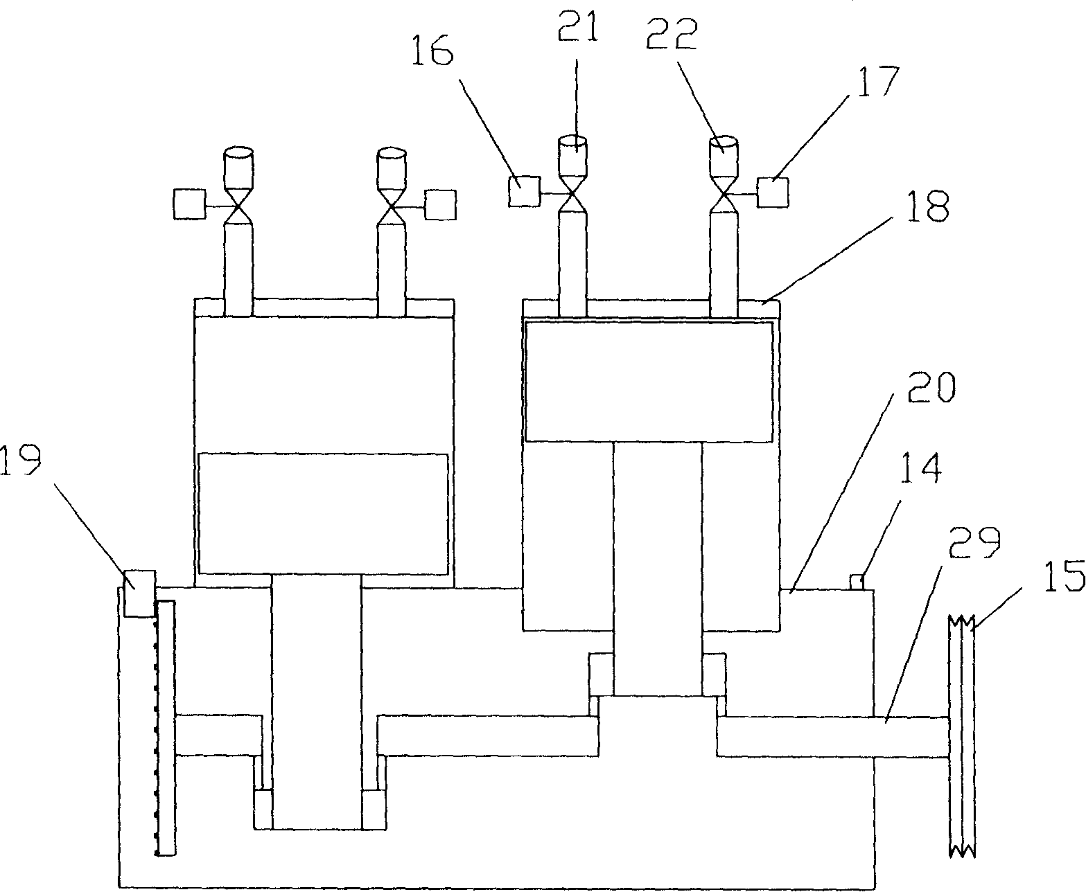
The invention relates to car carried engine used compressed air as power. It includes engine body, crank shaft, gear box, and belt sheave. The end of the crank shaft is connected with piston in cylinder. The cylinder cover is set intake pressure pipe and exhaust pipe. The engine body is set engine speed, dead point-distinguishing signal generator, and engine crank shaft dish rotating electric machinery. The crank shaft is set one way overrunning clutch. Compared with the existing technique, it has the advantages of environmental protection and simple structure.

Description

technical field [0001] The invention relates to a vehicle power equipment, in particular to a vehicle engine. Background technique [0002] Generally speaking, the power required by the engine used in vehicles is obtained by burning gasoline or diesel oil. As the current oil reserves are getting smaller and smaller, the price of oil is naturally getting higher and higher. [0003] Besides, the power obtained by burning fuel will cause air pollution and emission problems. No matter how complete the combustion of the machine, the combustion will also consume the oxygen in the atmosphere, produce carbon dioxide, and cause damage to the living environment of human beings; there are also harmful gases emitted, which will play an immeasurable harmful effect on the human body and the living environment of human beings. . [0004] In order to eliminate the above-mentioned hazards, environmentally friendly electric vehicles have been developed at present, but so far, they are diffi...

Claims


Application Information

Patent Timeline
IPC IPC(8): F01B1/02F01B23/02F01B25/00
Inventor 陈志新
Owner 陈志新
Learn More