Electron beam generating and controlling device

A control device, electron beam technology, applied in the direction of circuits, discharge tubes, electrical components, etc., can solve the problem of reducing the time resolution ability, and achieve the effect of reducing time dispersion and reducing moving distance.

Inactive Publication Date: 2006-10-25
INST OF PHYSICS - CHINESE ACAD OF SCI
View PDF0 Cites 18 Cited by
  • Summary
  • Abstract
  • Description
  • Claims
  • Application Information

AI Technical Summary

Problems solved by technology

But the deficiency of this set of devices is: if figure 1 As shown, after the electron beam is generated from the photocathode 1, it needs to pass through the anode 2, the magnetic lens 4, the X-direction deflection plate 5, the Y-direction deflection plate 6, and the scanning plate 7 to reac

Method used


Image

  • Electron beam generating and controlling device
  • Electron beam generating and controlling device
  • Electron beam generating and controlling device

Examples


Embodiment Construction

[0029] Below in conjunction with accompanying drawing and specific embodiment the present invention is described in further detail:

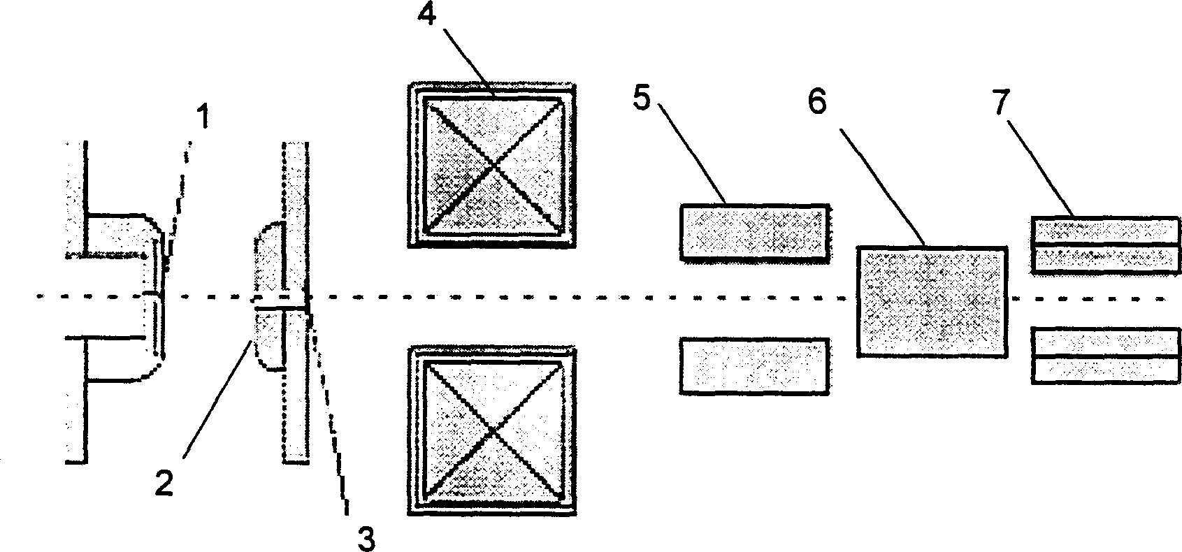
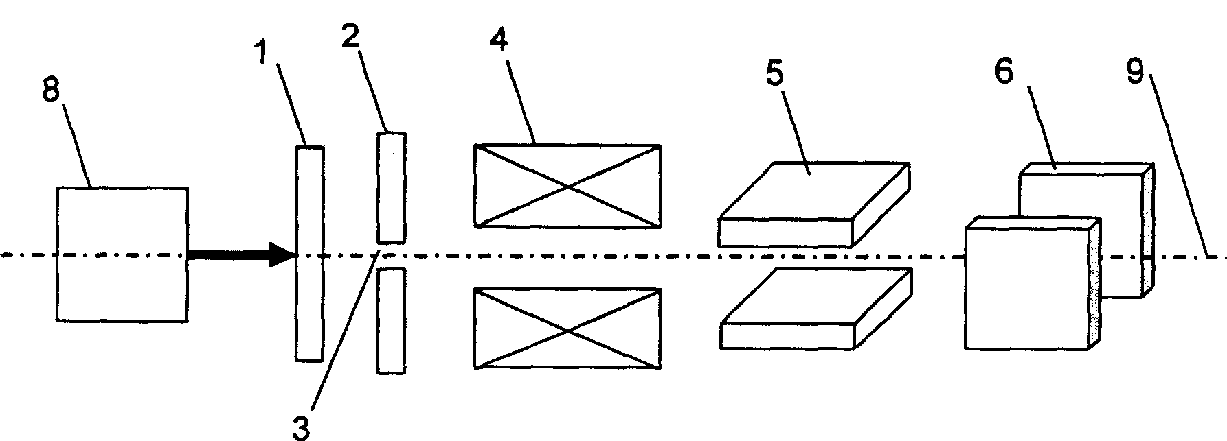
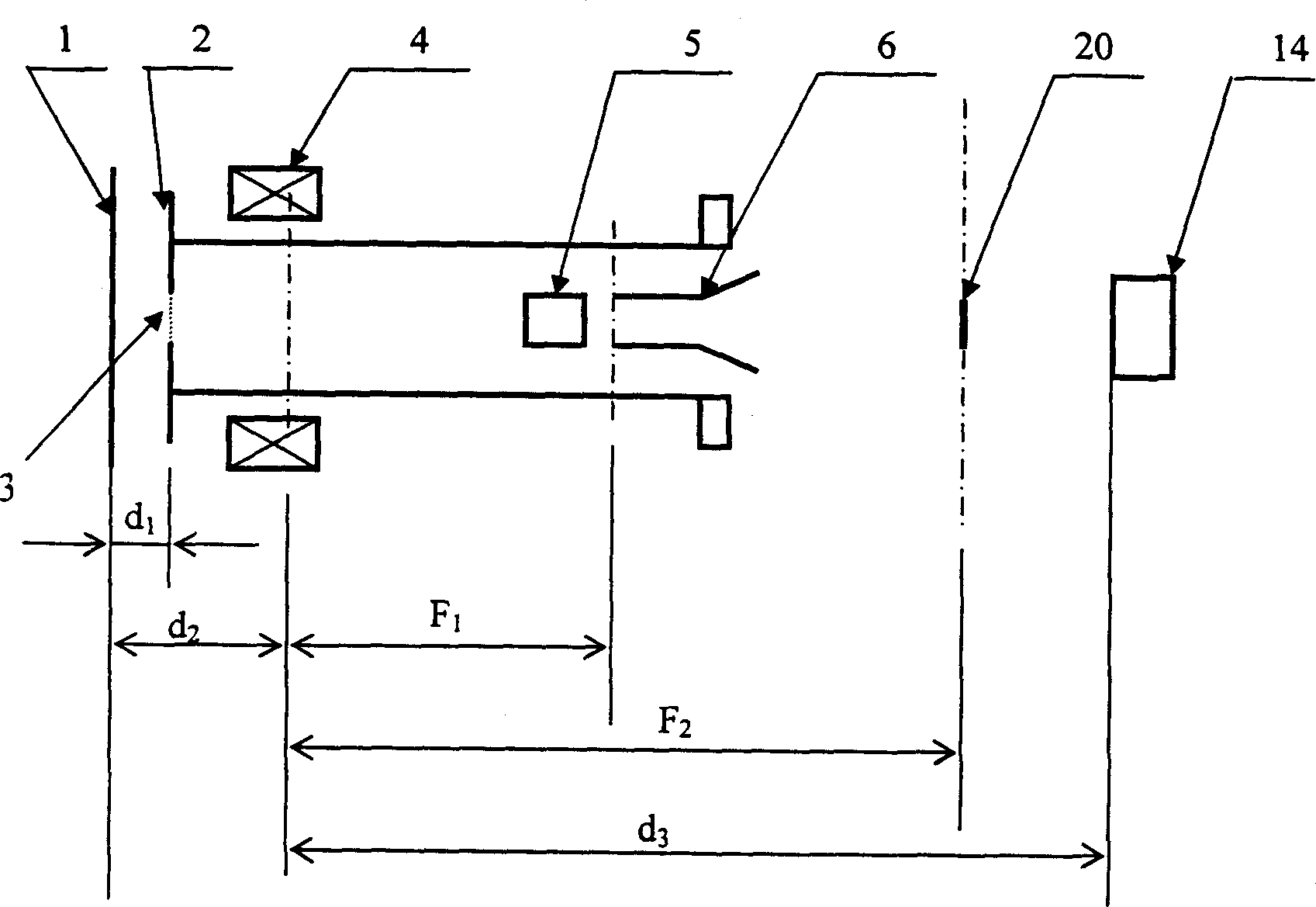
[0030] according to figure 2 , 3 An electron beam generating and controlling device is fabricated, wherein:

[0031] The femtosecond titanium sapphire laser of the ultraviolet triple frequency emitted by the laser source 8 has an output wavelength of 266nm and a pulse width of 30 femtoseconds;

[0032] The photocathode 1 adopts a silver film with a thickness of 40nm. After the femtosecond laser emitted by the laser source 8 interacts with the photocathode 1, an electron beam with an energy dispersion of less than 1eV is generated, and its time characteristic replicates the characteristics of an optical pulse;

[0033] The anode 2 is made of conventional electrode materials, and is placed parallel to the photocathode 1 face to face, and the distance between them is d 1 =5mm; a small hole 3 with a diameter of 100 microns is opened on the anode...


PUM

PropertyMeasurementUnit
Wavelengthaaaaaaaaaa
Diameteraaaaaaaaaa
Thicknessaaaaaaaaaa

Abstract

This invention discloses a generating and controlling device for femtosecond electronic beams, composed of a laser source, an optical cathode, an anode, a magnetic lens, a deflection board on the X-direction and a deflection board on Y-direction, in which, the laser source initiates a femtosecond-level super short pulse ultraviolet laser to drive optical cathode to generate the electronic beams with the energy dispersion degree less than 1eV and its time property replicates that of the optical pulse, the voltage on the anode is zero and negative high voltage is applied on the optical cathode, the electronic beam energy is accelerated to very high energy under the action of the electric field and the electronic wave length has very high space resolution ability, the deflection plate on the Y-direction is taken as the scan plate for testing its time property to test its pulse width of femtosecond electronic beams.

Description

technical field [0001] The invention relates to an electron beam generation and control device, in particular to a femtosecond electron beam generation and control device. Background technique [0002] In the research of laser technology, the appearance of femtosecond laser provides a powerful tool for scientists to study the ultrafast process of matter movement. But we know that the wavelength of the laser is too long, generally greater than 200nm, so the spatial resolution of using laser to study the motion of matter is far from enough. In order to obtain information with high spatial resolution, electrons or X-rays are generally used as detection means. [0003] Previous nanosecond and picosecond electron diffraction methods have played an important role in related experiments such as time-resolved reflection high-energy electron diffraction and gas phase electron diffraction. With the emergence of femtosecond laser, in order to further improve the time resolution, the ...

Claims


Application Information

Patent Timeline
IPC IPC(8): H01J37/06H01J1/34H01J37/063H01J37/147H01S3/00
Inventor 张杰刘运全梁文锡
Owner INST OF PHYSICS - CHINESE ACAD OF SCI
Why Eureka
Try Eureka