
Multi-channel column imaging fluorescent detector

A fluorescence detector, multi-channel technology, applied in the field of detectors, can solve the problems of light source intensity attenuation, limited quantitative detection, difficult to achieve, etc., and achieves the effect of reducing the size of the instrument, reducing the cost and volume, and being easy to implement.

Inactive Publication Date: 2006-11-29
TSINGHUA UNIV
View PDF0 Cites 26 Cited by
  • Summary
  • Abstract
  • Description
  • Claims
  • Application Information

AI Technical Summary

Problems solved by technology

However, the axial incidence has very strict requirements on the optical calibration system of the capillary and the laser, which is difficult to realize. Moreover, the light source intensity will be attenuated to a certain extent due to the absorption and scattering of the fluorescent sample band during the laser passing through the capillary, which limits the use of this system. Quantitative detection

Method used


Image

  • Multi-channel column imaging fluorescent detector
  • Multi-channel column imaging fluorescent detector
  • Multi-channel column imaging fluorescent detector

Examples


example 1

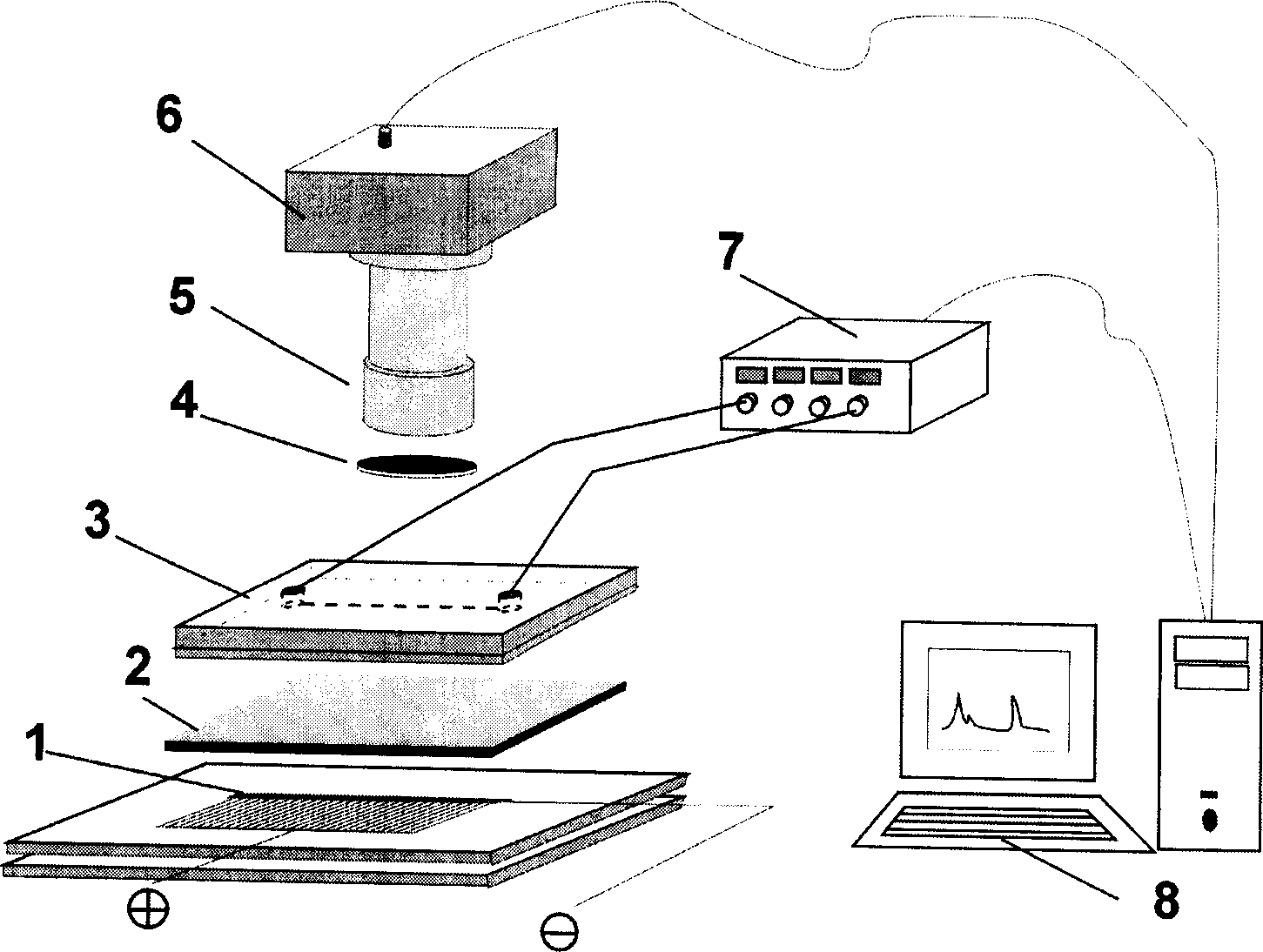
[0028] Example 1: Using fluorescent phycoerythrin (R-phycoerythrin) as a sample, it is configured in a buffer solution containing 2% ampholyte (ampholyte) and 1% hydroxypropyl methylcellulose (HPMC), and filled into a microfluidic chip Perform isoelectric focusing and separation, and use the present invention for detection. Before operation, the microfluidic chip channel was repeatedly rinsed with deionized water, filled with ultrasonically degassed buffer solution, and poured into the figure 1 Add 5 μL of the above solution to the sample cell, apply pressure to fill the microchannel, and then suck out the remaining solution with a pipette gun. Then add 5 μL 10mMH to the anode and cathode sample cells respectively 3 PO 4 and 20mM NaOH solution. Apply an electric field strength of 700V / cm between the anode and the cathode for isoelectric focusing electrophoresis. The electrophoretic spectra obtained at different time periods during the isoelectric focusing process are as fo...

example 2

[0029] Example 2: Three linear light sources are obtained by controlling the OLED light source, and isoelectric focusing electrophoresis is performed in a microfluidic chip with three parallel channels. The rest of the electrophoresis conditions are the same as in Example 1. The obtained results are as follows Figure 5 shown, where Figure 5 Among them, a, b, and c are the spectra obtained after isoelectric focusing of samples with the same concentration in three channels.

[0030] Through the above examples, it is illustrated that using OLED as a light source can be very conveniently used in the microfluidic chip isoelectric focusing electrophoresis system. Compared with traditional detectors, it has the characteristics of small size, low cost, and simple structure, and it is easy to realize multi-channel simultaneous detection. the goal of.


PUM

PropertyMeasurementUnit
thicknessaaaaaaaaaa
thicknessaaaaaaaaaa
thicknessaaaaaaaaaa

Abstract

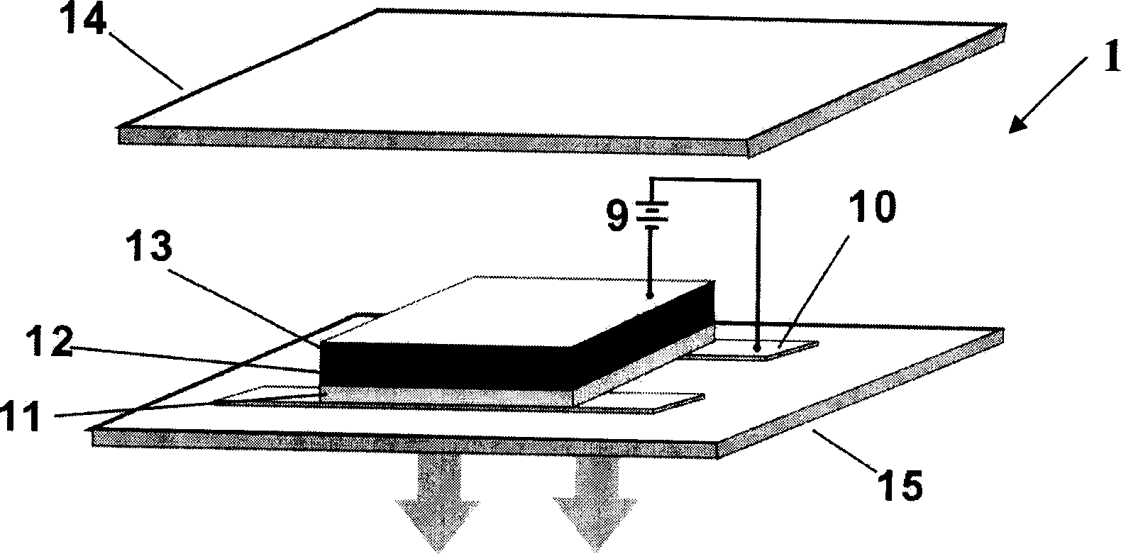
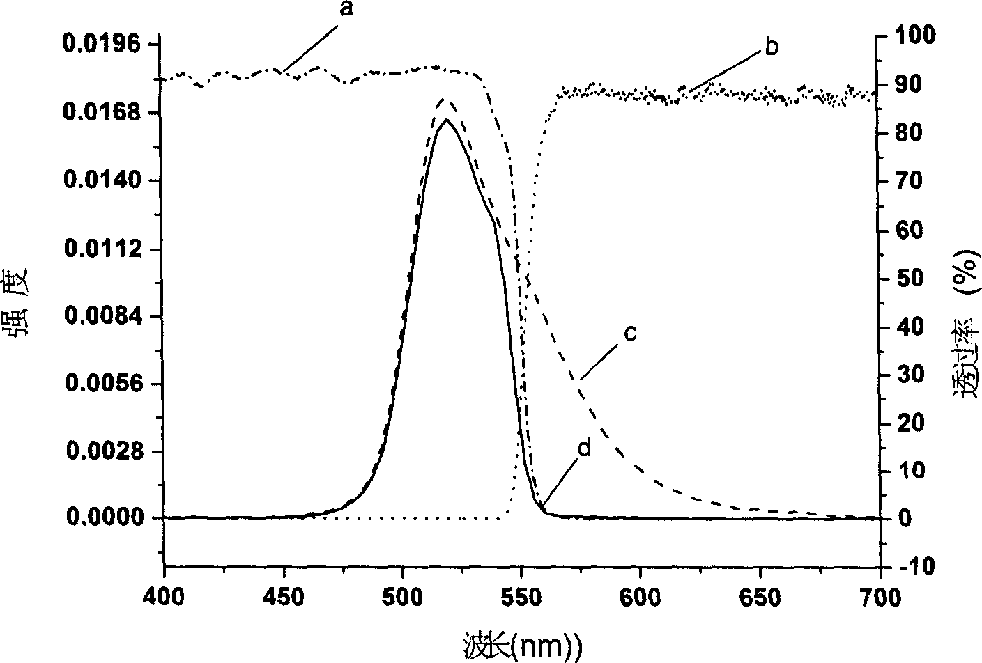
The invention relates to a multichannel column imaging fluorescence detector, comprising: excitation light source, microflow control chip, emitted light filter plate, high voltage power supply and computer control system, in turn arranged, and characterized in that: the excitation light source adopts small-molecular organic LED and plural electrodes of the light source is connected by external circuit so as to make it emit single linear light source or plural different-length linear light sources according to the requirements; the ultrathin excited light filter plate is arranged between the excitation light source and microflow control chip, lens and charge coupling detector are arranged on top of the emitted light filter plate. And the invention can conveniently implement column imaging detection mode without optical fiber, cylindrical prism and complex optical components, further reducing bulk and cost and effectively improving detection sensitivity.

Description

technical field [0001] The invention relates to a detector, in particular to a column imaging fluorescence detector which is used in an isoelectric focusing electrophoresis system of a microfluidic chip and adopts an organic light-emitting diode (OLED) as a light source and can realize multi-channel detection. Background technique [0002] Protein is a kind of ampholyte molecule. In the pH environment greater than its isoelectric point, it will dissociate into negatively charged ions, and electrophoresis to the positive electrode in the electric field; while in the pH environment lower than its isoelectric point, it will dissociate into Positively charged ions swim toward the negative electrode until they are in a pH environment equal to their isoelectric point, that is, when the net charge is zero (ie isoelectric point, pI), they do not stop. At this time, the migration of charged molecules under the action of an electric field Equilibrium with diffusion movement. If this ...

Claims


Application Information

Patent Timeline
Patent Type & Authority Applications(China)
IPC IPC(8): G01N21/64G01N27/447H05B33/08H05B44/00
CPCY02B20/36Y02B20/343Y02B20/30
Inventor 罗国安姚波王立铎任康宁杨辉华王义明邱勇
Owner TSINGHUA UNIV
Learn More