
Processing method for position and light of built-in tilt Bragg raster containing optical waveguide

A technology of Bragg grating and optical waveguide, which is applied in the coupling of optical waveguide, spectrometry/spectrophotometry/monochromator, light guide, etc., can solve the difficulty of measuring the mode power distribution of multimode optical fiber, which is difficult to apply, etc. question

Inactive Publication Date: 2006-11-29
SOUTHEAST UNIV +1
View PDF0 Cites 19 Cited by
  • Summary
  • Abstract
  • Description
  • Claims
  • Application Information

AI Technical Summary

Problems solved by technology

[0004] Until now, it has been difficult to measure the mode power distribution of multimode fibers
Although the mode power distribution of multimode fibers can be obtained by near-field or far-field measurements, this method relies on the prior acquisition of the refractive index profile, fiber end-face quality, and alignment of the optical system, making this method difficult to apply

Method used

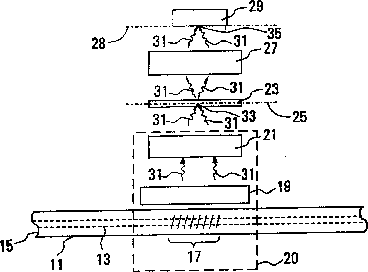

Image

  • Processing method for position and light of built-in tilt Bragg raster containing optical waveguide
  • Processing method for position and light of built-in tilt Bragg raster containing optical waveguide
  • Processing method for position and light of built-in tilt Bragg raster containing optical waveguide

Examples


Embodiment Construction

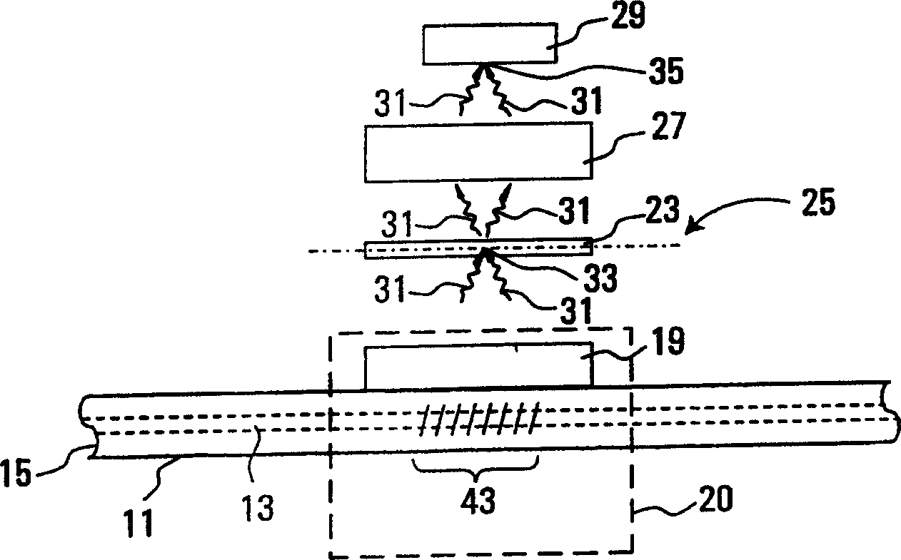
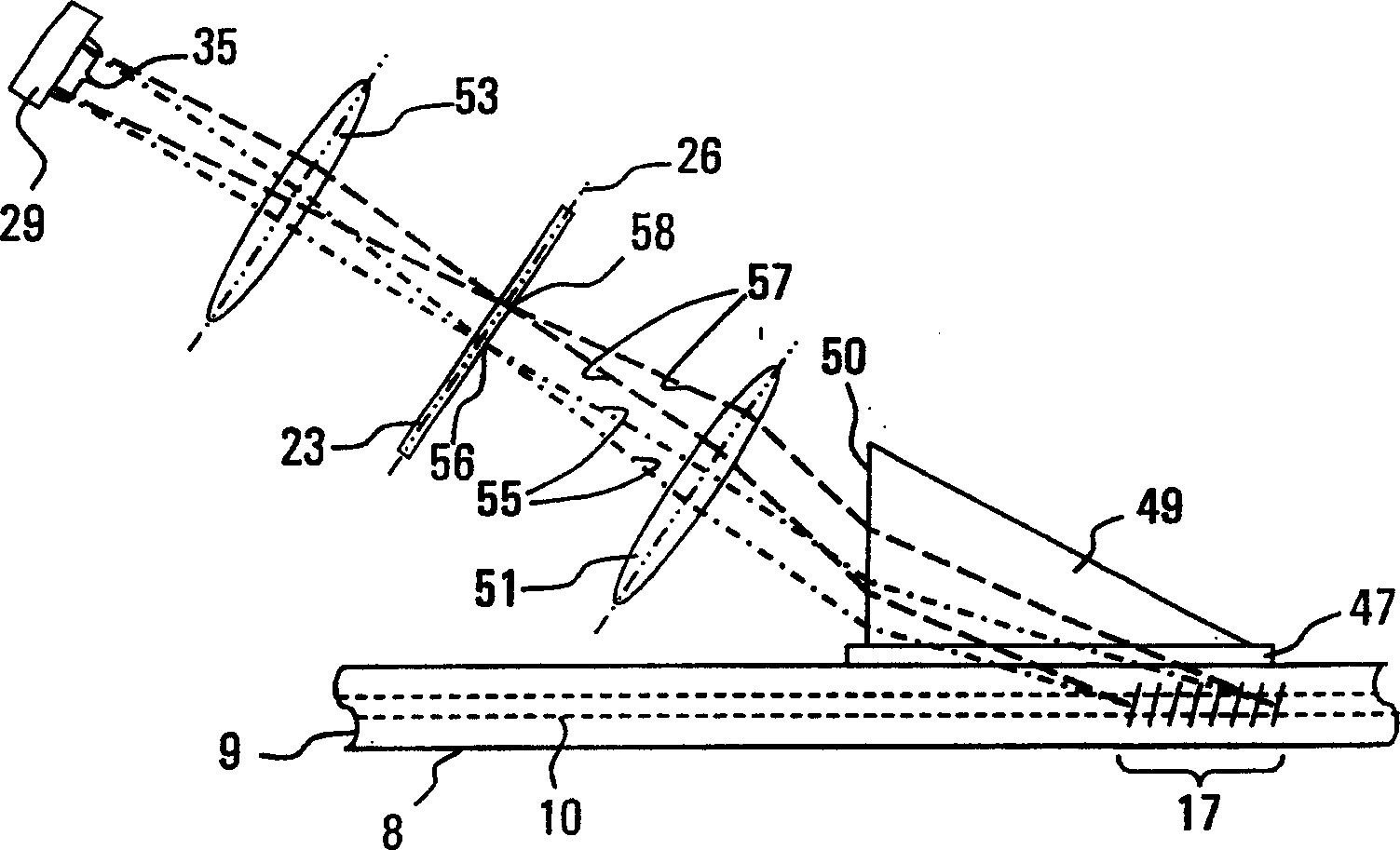
[0061] figure 1 is a schematic diagram of an example of an optical device corresponding to an example of the present invention. Optical waveguide 11 includes a core 13 and cladding 15 . A sloped refractive index grating (hereinafter referred to as "grating") 17 is fabricated in the optical waveguide 11 by conventional methods. For example, the optical waveguide 11 is a conventional silica fiber, and the grating 17 is written into the fiber using a phase mask or optical holography. Slanted grating 17 can make it can set the light wavelength range (for example including wavelength λ) by selection i ) One or more guided modes couple into radiative modes. It is further advantageous if an optical coupling device 19 is used, which cooperates with the optical waveguide 11 so that the cladding 15 of the optical waveguide 11 does not have light-binding properties. The light coupled out of the optical waveguide 11 becomes a radiation ray 31 . A primary focusing device 21 focuses th...


PUM


Abstract

The invention is commonly (widely or generally) characterized in being an optical device, where a light waveguide is in the optical device and an inclined grating is in the optical device to couple in one or plural irradiating beams through guide mode; light irradiated from the inclined grating is focused into intermediate image in the preset position on a middle image plane, and the position of the intermediate image depends on light wavelength and effective refractive index of the guide mode. And the invention can place a spatial light modulator to control phase and / or amplitude of light beam. More remarkably, the invention comprises a last-stage focusing device to focus light transmitted by the spatial light modulator into last stage image in local region, so as to improve light strength, i.e. improving detecting sensitivity, where the last- stage focusing device can be a lens. And the invention also comprises a light receiver, which can be a optical fiber detector, or a last-stage image detecting light detector array.

Description

technical field [0001] The invention relates to a tilted Bragg (Bragg) grating embedded in an optical waveguide and the detection and processing of optical signals. Background technique [0002] In fiber optic communication and sensor systems, a tilted fiber Bragg grating embedded in an optical waveguide is an effective way to couple the guided light inside the waveguide out of the optical waveguide. Tilted Braggs have many potential applications, for example: wavelength monitors, optical spectrum analyzers (OSAs) or for measuring the modal power distribution of multimode waveguides. [0003] Spectrum analyzer is an important experimental instrument commonly used in the fields of chemistry, physics and biology. Improving the sensitivity and resolution of optical spectrum analyzers can improve the ability to analyze the structure and concentration of materials, expand the capacity and reliability of optical communication systems, and provide the ability to sense weak signals...

Claims


Application Information

Patent Timeline
IPC IPC(8): G02B6/26G02B6/32G02B6/34
CPCG01J3/0205G02B6/2852G02B6/29323G01J3/1895G01J3/0229G01J3/02G01J3/0256G02B6/4215
Inventor 杨春徐长青
Owner SOUTHEAST UNIV
Learn More