High performance type three-dimensional cell

A high-output, battery technology, applied in the direction of large flat batteries/batteries, nickel storage batteries, primary batteries, etc., can solve problems such as increased resistance, increased production time, and reduced performance

Inactive Publication Date: 2007-01-10
KAWASAKI HEAVY IND LTD +1
View PDF4 Cites 6 Cited by
  • Summary
  • Abstract
  • Description
  • Claims
  • Application Information

AI Technical Summary

Problems solved by technology

The problem here is that resistance increases, manufacturing cost increases, and manufacturing time increases due to soldering connection of multiple planar active material sheets.
[0019] Although a single dry battery has good performance, when it is necessary to make a large-capacity battery, once multiple single batteries are connected in parallel or in series, the voltage will drop and the performance will only decrease due to the contact resistance of the external terminals. Battery
In addition, in the case of a large-capacity battery like an industrial battery, as mentioned above, it is impossible to obtain a high-performance battery due to the basic structural problem of many welding points.

Method used

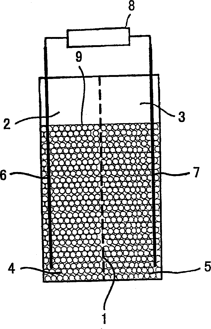
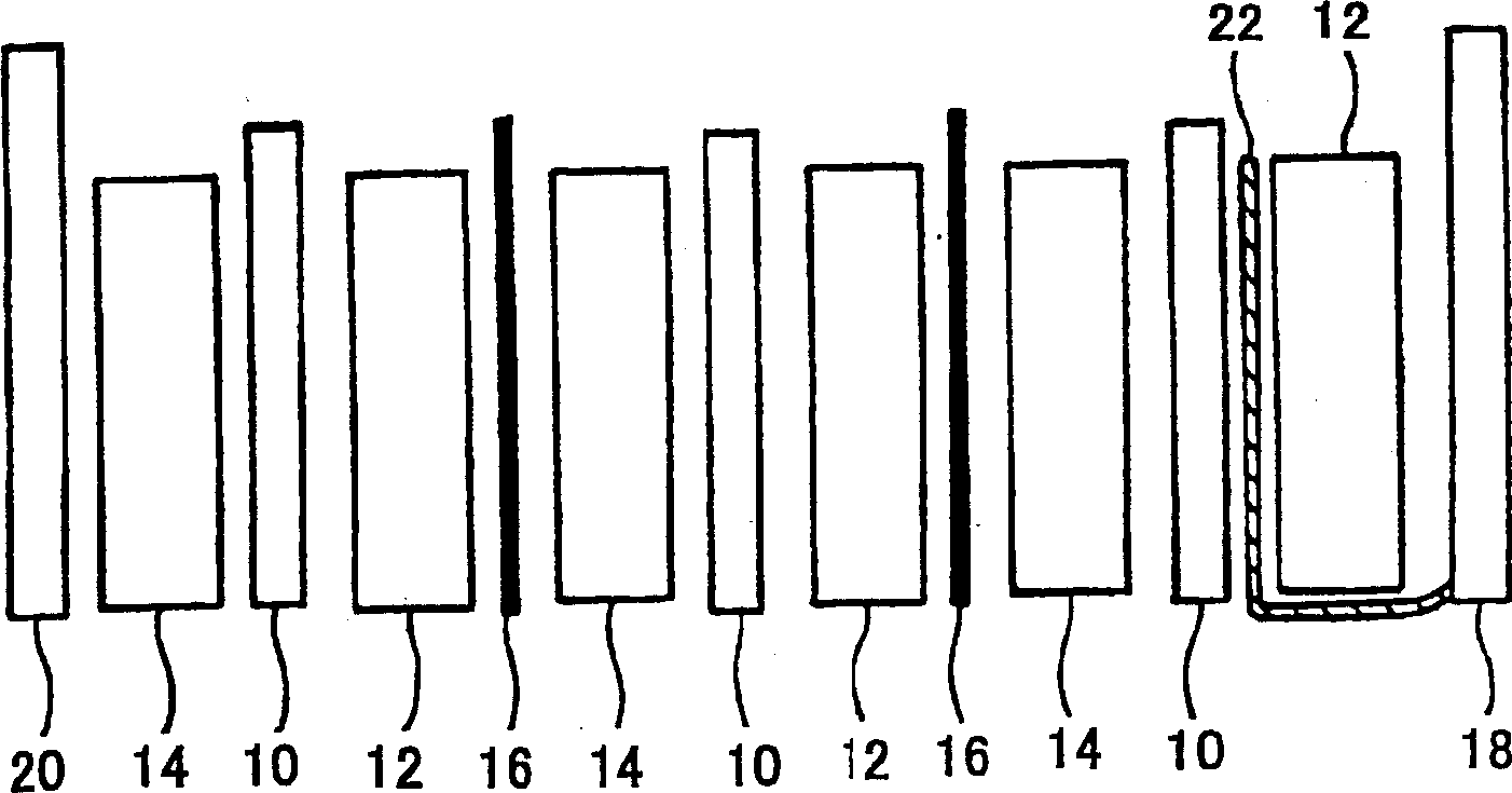
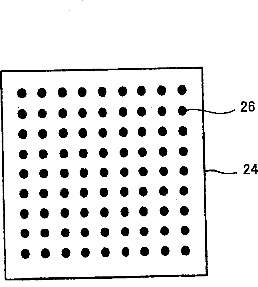

Image

  • High performance type three-dimensional cell
  • High performance type three-dimensional cell
  • High performance type three-dimensional cell

Examples


Embodiment 1

[0136] Put 150 grams of granular graphite (acetylene carbon black) into a Henschel mixer with a volume of 10 liters, and stir at a speed of 1000 rpm for about 3 minutes to fully disperse the granular graphite. Further, 1000 g of nickel hydroxide powder and 100 g of carbon fiber (trade name "DONER-247") were added thereto, and stirred at 1000 rpm for about 3 minutes. Further, 150 g of ethylene-vinyl acetate copolymer was added thereto, and stirring and mixing were carried out for 10 minutes at a temperature above the softening temperature and below 130° C. A separation layer (nylon non-woven fabric) is pre-laid on the bottom of the frame with a cross-sectional size of 100mm×100mm, and then the nickel hydroxide mixture is filled thereon. Press molding is performed by applying a pressure of 0.1 MPa while heating from above, and the temperature is lowered in this state to harden the resin. The molded object is taken out from the mold to obtain an electrode material in which the a...

Embodiment 2

[0138] The nickel hydroxide powder was mixed and stirred with the conductive filler and the resin in the same manner as in Example 1 to obtain a nickel hydroxide mixture. A separation layer (nylon non-woven fabric) is pre-laid on the bottom of the frame with a cross-sectional size of 100mm×100mm, and then the nickel hydroxide mixture is filled thereon. The resin is hardened by cooling in the mold without applying pressure. The molded product was taken out from the mold to obtain an electrode material in which the active material and the separator were integrally molded.

Embodiment 3

[0140]The nickel hydroxide powder was mixed and stirred with the conductive filler and the resin in the same manner as in Example 1 to obtain a nickel hydroxide mixture. A current collector (nickel plate) is laid in advance on the bottom of a frame with a cross-sectional size of 100mm×100mm, and then the nickel hydroxide mixture is filled thereon. Press molding is performed by applying a pressure of 0.1 MPa while heating from above, and the temperature is lowered in this state to harden the resin. The molded product was taken out from the mold to obtain an electrode material in which the active material and the current collector were integrally molded.


PUM

PropertyMeasurementUnit
softening pointaaaaaaaaaa
particle diameteraaaaaaaaaa

Abstract

When producing an electrode for use in a three-dimensional battery, an active material is combined with at least one of a separator, a dividing wall, and a current collector for simultaneous formation. Both the dividing wall and the current collector are planar or are so formed as to have projected portions in needle, plate, wave, particle, or the like form. Both the dividing wall and the current collector may be provided with a cooling structure. As an additional current collector, an ion permeable current collector, which has voids therein, permits passage of ions, and exhibits electrical conductive properties, is provided.

Description

[0001] This application is an invention with the application number 02818299.5 (international application number PCT / JP02 / 09409), the application date is September 13, 2002, and the invention name is "three-dimensional battery and its electrode structure and the manufacturing method of three-dimensional battery electrode material" A divisional application of a patent application. technical field [0002] The present invention relates to an electrode structure and a manufacturing method of a three-dimensional battery formed by filling active materials in the form of powder, granule, or plate, and a high-output three-dimensional battery that is based on a serpentine unit unit and can be easily upgraded to a higher level. Battery. Background technique [0003] The present invention relates to a three-dimensional battery, and the problems to be solved by the present invention can be divided into the following problems in relation to the prior art. [0004] That is, the first su...

Claims


Application Information

Patent Timeline
Patent Type & Authority Applications(China)
IPC IPC(8): H01M10/28H01M4/24H01M2/16H01M4/66H01M4/62H01M6/00H01M4/32H01M10/04H01M10/30H01M50/443H01M50/463H01M50/528
CPCY02E60/124H01M4/66H01M10/0413H01M4/762H01M10/0459H01M4/70H01M10/28H01M10/26H01M2/18H01M10/30H01M2/16H01M2/1673Y02E60/10H01M50/46H01M50/463Y02P70/50H01M50/443H01M4/32H01M4/24H01M4/26
Inventor 堤香津雄西村和也光田进谷川贵仁
Owner KAWASAKI HEAVY IND LTD
Why Eureka
Try Eureka