2 mu m bonded monoblock and non-planar longitudinal-mode laser

A single longitudinal mode laser and laser technology, applied in the laser field, can solve problems such as limiting the efficient operation of lasers, complex design of non-planar monolithic crystals, and certain difficulties in processing

Inactive Publication Date: 2007-01-17
BEIJING INSTITUTE OF TECHNOLOGYGY
View PDF0 Cites 7 Cited by
  • Summary
  • Abstract
  • Description
  • Claims
  • Application Information

AI Technical Summary

Problems solved by technology

[0004] The advantages of non-planar unidirectional traveling-wave ring cavity lasers are monolithic, good stability, and low frequency and power noise. The main disadvantage is that the design of non-planar monolithic crystals is complicated, and processing is difficult, requiring larger-sized laser crystals. Material
For the realization of 2 μm by using a single non-planar annular cavity, it is difficult to obtain large-diameter crystals with good optical uniformity from crystal materials (such as Tm:YAG, Tm:LuAG, Tm, Ho:YAG, Ho:YAG, etc.). The reabsorption in the 2μm band is serious, which limits the efficient operation of 2μm monolithic non-planar ring cavity lasers

Method used


Image

  • 2 mu m bonded monoblock and non-planar longitudinal-mode laser
  • 2 mu m bonded monoblock and non-planar longitudinal-mode laser
  • 2 mu m bonded monoblock and non-planar longitudinal-mode laser

Examples


Embodiment 1

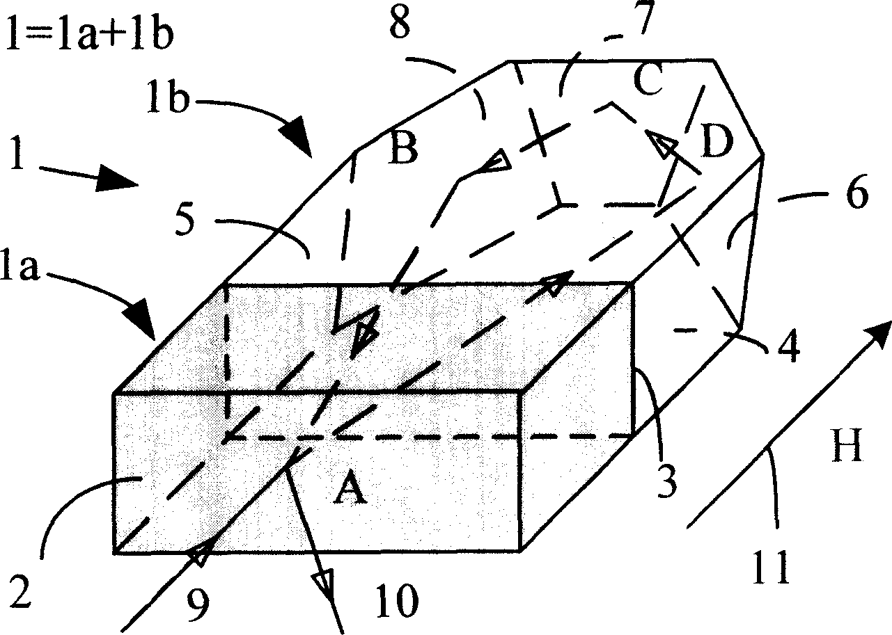
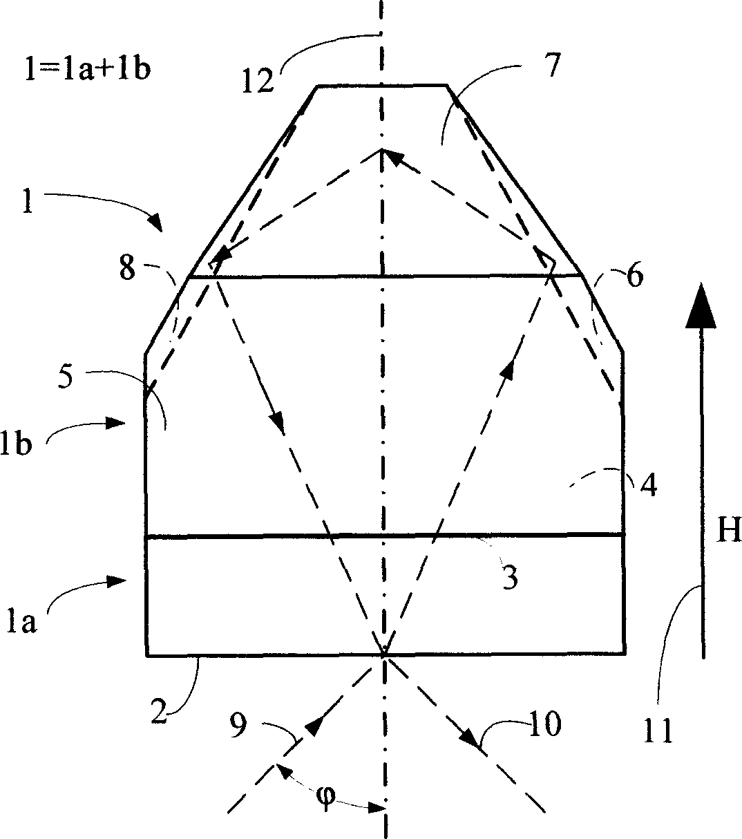
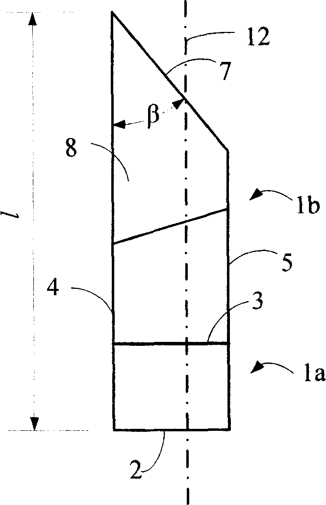
[0011] Example 1: figure 1 It is a schematic diagram of the structure of a bonded monolithic non-planar ring cavity to achieve 2μm single longitudinal mode laser oscillation. The 2μm laser crystal (1a) and the non-doped crystal (1b) are bonded into a monolithic laser crystal (1) to form the resonant cavity of the laser. Point A is both the incident point of the pump light (9) and the exit point of the oscillating laser light (10), using the phase delay of the light wave on the total reflection surface of the points B, C and D in the cavity, introduced by the external magnetic field H Faraday rotation effect, and by coating on the crystal end face (2) where point A is located, the light waves propagating clockwise and counterclockwise in the cavity have different intrinsic polarization states, and the s-polarized light in each direction and The p-polarized light has different reflection coefficients for the output surface, and finally a certain polarization state in one directi...

Embodiment 2

[0012] Example 2: figure 1 It is also a schematic diagram of the structure of a quasi-monolithic non-planar ring cavity that realizes 2μm single longitudinal mode laser oscillation. The 2μm laser crystal (1a) is coated with an anti-reflection coating on the end face (3), and the end face (3) of the non-doped crystal (1b) is also coated The oscillating light anti-reflection coating is closely attached to form a quasi-monolithic laser crystal (1). The point A on the 2μm laser crystal (1a) is not only the incident point of the pump light (9) but also the exit point of the oscillating laser (10). Retardation, the Faraday rotation optical effect introduced by the external magnetic field H, and by coating the crystal end face (2) where point A is located, the light waves propagating clockwise and counterclockwise in the cavity have different intrinsic polarization states, and The s-polarized light and p-polarized light in each direction have different reflection coefficients for th...


PUM

PropertyMeasurementUnit
Total lengthaaaaaaaaaa
Thicknessaaaaaaaaaa

Abstract

The invention is concerned with the laser that uses the doping crystal and non-doping crystal diffused bonding or combinative place to form non-plane ring cavity creating 2 mum single longitudinal module laser output. The laser medium of the laser is the single non-plane ring crystal that can create 2 mum laser output the doping crystal (such as Tm:YAG, Tm:LuAG, Tm,Ho:YAG, Ho:YAG crystal etc.) and the non-doping crystal (such as non-doping YAG crystal) diffused bonding or combinative place to form single non-plane ring crystal, uses the semiconductor laser as the pump source that the absorb wavelength of the central wavelength and the doping crystal is accordant, can create the 2 mum single longitudinal module laser output. The characteristic of the invention is: uses the diffused bonding or combinative place to form compound crystal as the working material, uses the single non-plane ring cavity as the laser resonance cavity, and creates 2 mum single longitudinal module laser output.

Description

technical field [0001] The invention belongs to the field of laser technology. Background technique [0002] 2μm band lasers have important application prospects in laser medicine, laser radar, laser ranging and other fields. Since there are multiple water absorption peaks in the 2μm band, and human tissue contains a lot of water, the 2μm band laser can achieve precise cutting of biological tissues, and can also be used as a precision medical instrument for doctors to remove cartilage and other hard tissues. At the same time, 2μm band lasers also have important application value in target detection fields such as lidar and laser ranging, and can be used as coherent Doppler wind radar, laser range finder, CO2 in the air, etc. 2 and water vapor content measurement radar etc. light source. [0003] 2μm-band solid-state lasers operating in a single longitudinal mode are required in most applications. According to the current technology, the methods that can realize the operat...

Claims


Application Information

Patent Timeline
IPC IPC(8): H01S3/06H01S3/083H01S3/16H01S3/10H01S3/0941H01S3/00
Inventor 高春清高明伟林志锋张秀勇李家泽魏光辉
Owner BEIJING INSTITUTE OF TECHNOLOGYGY
Why Eureka
Try Eureka