Lifting device and method for processing alloy wire with continuous or step taper at end
A pulling device and alloy wire technology are applied in the field of mechanical pulling device and processing ultra-fine metal alloy wire, which can solve the problems of surface work hardening, expensive equipment and high processing cost, achieve low processing cost and facilitate popularization The effect of high precision of application and dimensional control
- Summary
- Abstract
- Description
- Claims
- Application Information
AI Technical Summary
Problems solved by technology
Method used
Image
Examples
specific Embodiment approach 1
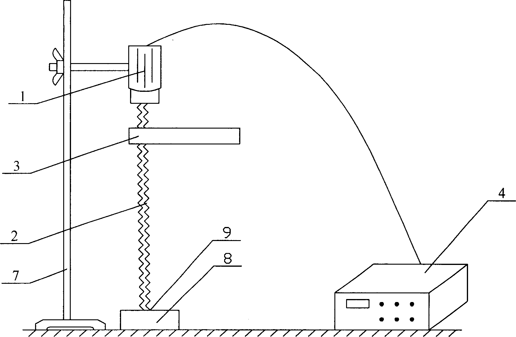
[0012] Specific implementation manner one: such as figure 1 As shown, the lifting device of this embodiment is composed of a motor 1, a lead screw 2, a lifting motion device 3, a peripheral control device 4 that controls the direction, speed, and number of lifting, and a bracket 7. The motor 1 is fixed on the bracket 7. The upper end of the bracket 7 is fixed on the table, the electrical input end of the motor 1 is connected to the output end of the peripheral control device 4 that controls the pulling direction, speed, and times. The output shaft of the motor is connected to the upper end of the screw 2. , The lower end of the lead screw 2 is fixed in the blind hole 9 of the fixed body 8, and the lifting motion device 3 is sleeved on the lead screw 2 through a nut.
[0013] Working principle: The screw 2 is rotated by the motor 1, and the lifting motion device 3, which is sleeved on the screw with a nut, realizes the lifting movement through the forward and reverse rotation of t...
specific Embodiment approach 2
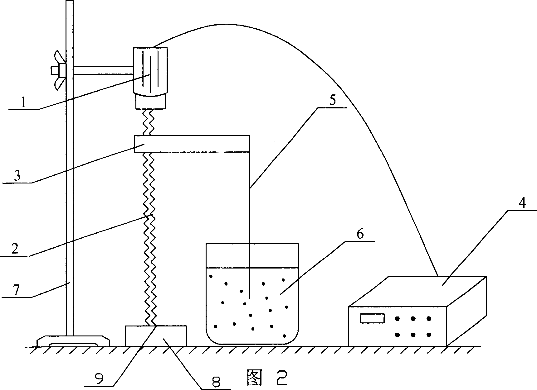
[0015] Second embodiment: As shown in Figure 2, the difference between this embodiment and the first embodiment is that in the actual production process, an etching processing fluid tank 6 is also required, and the etching processing fluid tank 6 is set on the wire 5 to be processed. The upper end is suspended on the lifting motion device 3 and the lower end can be vertically immersed in the corrosion processing liquid tank 6.
specific Embodiment approach 3
[0016] Specific embodiment 3: This embodiment is a method for processing a near-equal atomic ratio nickel-titanium alloy guide wire with a specific size at the tapered distal end, which sequentially includes the following steps:
[0017] a. Prepare a certain concentration of hydrofluoric acid (HF), nitric acid (HNO) in the temperature range of 50-80℃ 3 ) And water (H 2 O) The mixed solution, in which the volume percentage of hydrofluoric acid is generally not more than 20%, and the volume percentage of nitric acid is generally between 20-50%, which is used as a corrosion processing solution.
[0018] b. As shown in Figure 2, fix the wire on a device that uses a servo motor as the power to drive the screw and nut to achieve pulling, and through the peripheral control that controls the pulling direction, speed, and times The device is used to realize the immersion and extraction of the wire in the corrosion processing solution. By using the pulling device to pull the processed wire ...
PUM
| Property | Measurement | Unit |
|---|---|---|
| diameter | aaaaa | aaaaa |
Abstract
Description
Claims
Application Information
 - R&D
- Intellectual Property
- Life Sciences
- Materials
- Tech Scout
- Unparalleled Data Quality
- Higher Quality Content
- 60% Fewer Hallucinations
Browse by: Latest US Patents, China's latest patents, Technical Efficacy Thesaurus, Application Domain, Technology Topic, Popular Technical Reports.
© 2025 PatSnap. All rights reserved.Legal|Privacy policy|Modern Slavery Act Transparency Statement|Sitemap|About US| Contact US: help@patsnap.com


