Digital control method for spiral pressure machine transmission and digital control spiral pressure machine

A screw press, industrial control technology, applied in the direction of press, punching machine, computer control, etc., can solve the problems of fragility, complex control circuit, difficult to popularize, etc., to extend the life of the mold, high forming accuracy, and simplify the structure. Effect

Inactive Publication Date: 2007-05-30
SHANDONG KEHUI POWER AUTOMATION
View PDF1 Cites 11 Cited by
  • Summary
  • Abstract
  • Description
  • Claims
  • Application Information

AI Technical Summary

Problems solved by technology

On July 14, 2004, the State Intellectual Property Office of the People's Republic of China authorized the utility model patent No. ZL03254142.2 named "Electric Screw Press". It uses an AC servo motor to drive the screw press through gear transmission. Because the motor The cost of the control system is high, the control circuit is complex, fragile, and difficult to promote
The main problem of the above-mentioned and existing screw presses is that the angular displacement and angular velocity of the screw, that is, the displacement and speed of the slider, cannot be numerically controlled.
At present, there is no screw press that can realize the numerical control of slider displacement and speed in industrial production.

Method used


Image

  • Digital control method for spiral pressure machine transmission and digital control spiral pressure machine
  • Digital control method for spiral pressure machine transmission and digital control spiral pressure machine
  • Digital control method for spiral pressure machine transmission and digital control spiral pressure machine

Examples


Embodiment 1

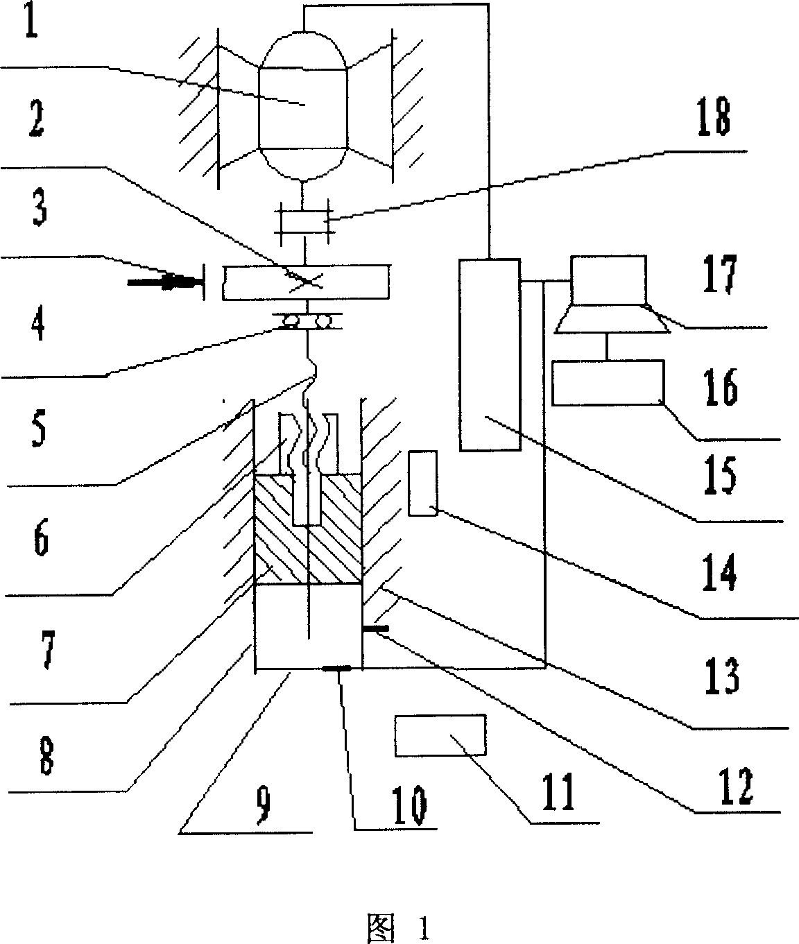
[0024] As shown in Figure 1, the switched reluctance speed regulating motor 1 is installed on the fuselage 13, the output shaft is connected with the flywheel 2 through the coupling 18, the screw rod 5 is located at the central axis of the fuselage 13 and is installed on the fuselage through the bearing 4 13, the upper end of the screw rod 5 is connected with the flywheel 2 as a whole, the screw rod 5 and the nut 6 cooperate with the screw pair, the nut 6 and the slider 7 are connected as a whole, and the guide rail 8 is installed symmetrically with the central axis in the fuselage 13, and the guide rail 8 and the slider The block 7 is slidably fitted, the force sensor 10 is installed in the workbench 9, the infrared pyroelectric sensor 12 is installed on the fuselage 13 in the dangerous area of ​​operation, the brake 3 is fixed on the fuselage 13, and its brake block is hugged on the flywheel 2 .

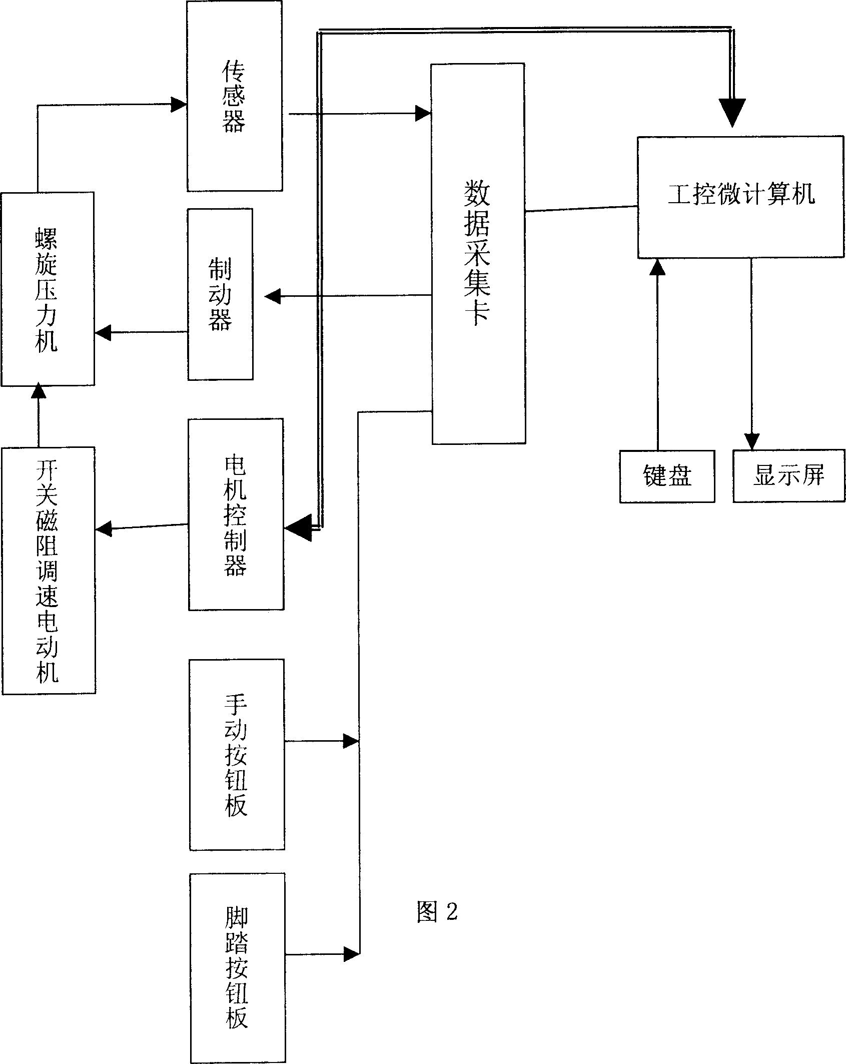
[0025] As shown in Figure 2, the industrial control microcomputer is connected...

Embodiment 2

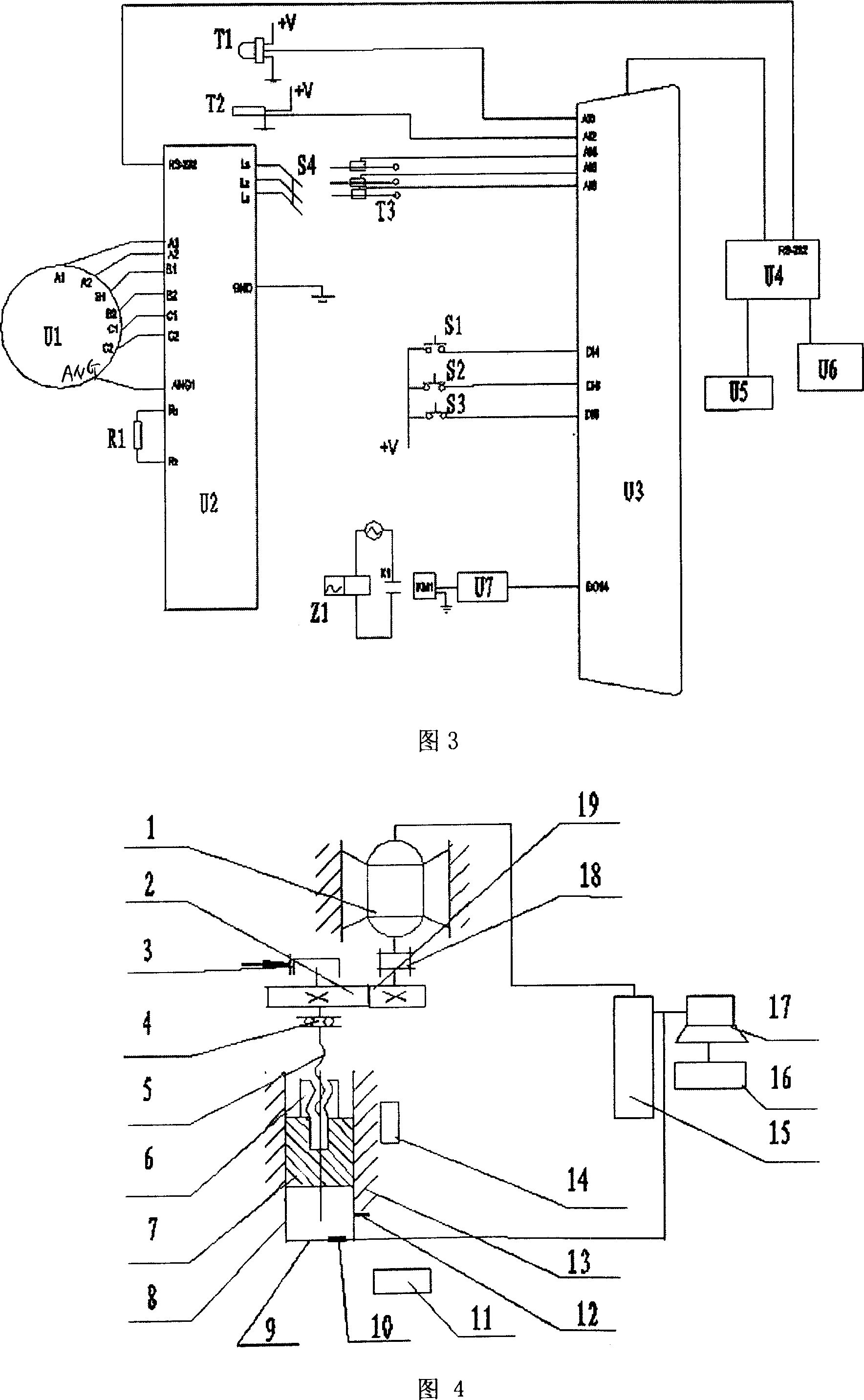
[0030] As shown in Figure 4, in the CNC screw press of the present invention, the switched reluctance speed regulating motor 1 is installed on the body 13, and the output shaft of the switched reluctance speed regulating motor 1 is connected with the pinion 19 through a shaft coupling 18, and the pinion 19 meshes with the flywheel 2, the upper end of the screw 5 is connected with the flywheel 2 as a whole, the screw 5 and the nut 6 cooperate with a screw pair, the nut 6 and the slider 7 are connected as a whole, and the guide rail 8 is installed symmetrically with the central axis in the fuselage 13, The guide rail 8 is slidably matched with the slider 7, the load cell 10 is installed in the workbench 9, the infrared pyroelectric sensor 12 is installed on the fuselage 13 in the dangerous area of ​​operation, the brake 3 is fixed on the fuselage 13, and its brake block is held On the brake pads of flywheel 2.

Embodiment 3-4

[0032] As shown in Figure 5-6, the change of the screw press is mainly in the transmission mechanism. For example, in Figure 5, the output shaft of the switched reluctance speed regulating motor 1 is connected with the flywheel 2 through the coupling 18, and the screw 5 is connected with the flywheel 2 as In one piece, the screw 5 is installed on the fuselage 13 through the thrust bearing 4, the screw 5 and the nut 6 cooperate with a screw pair, the nut 6 and the wedge 20 are connected as one, and the wedge 20 and the slider 7 slide and fit through the dovetail slideway. A guide rail 8 is installed in the fuselage 13, and the guide rail 8 is slidably matched with the slide block 7. The load cell 10 is installed in the workbench 9, the infrared pyroelectric sensor 12 is installed on the fuselage 13 in the operation danger zone, and the brake 3 is fixed on the machine. On the body 13, its brake block is hugged on the brake pad of flywheel 2. When the screw rod 5 rotates, the nut...


PUM


Abstract

The screw extruder drive digital control comprises inputting running data by the operator and work station control computer control motor running, with the motor using switch magnetic resistance speed regulating motor, based on the input data, through the calculation of the work station control computer control motor, switch magnetic resistance speed regulating motor driving the extrusion of the screw. Switch magnetic speed regulating motor provides power to spiral compressor, through regulating angular displacement and velocity of the speed regulating motro to control the displacement and speed change of the slide of the compressor, realizing digital control fo the spiral compressor with simple structure, free from speed regulation, easy control of the slide displacement velocity.

Description

technical field [0001] The invention relates to a numerical control method for transmission of a screw press and a numerical control screw press, which belong to the field of material forming equipment. Background technique [0002] Because the electric screw press does not use low-efficiency friction transmission, it has the shortest transmission chain and high efficiency, so technicians from various countries continue to conduct research. German Lasco Company and Weingarten Company produced electric screw presses using variable frequency speed regulation motor technology, and Japanese Enomoto Company also developed a screw press driven by AC servo motors in 2001. On July 14, 2004, the State Intellectual Property Office of the People's Republic of China authorized the utility model patent No. ZL03254142.2 named "Electric Screw Press". It uses an AC servo motor to drive the screw press through gear transmission. Because the motor The cost of the control system is high, the ...

Claims


Application Information

Patent Timeline
Patent Type & Authority Applications(China)
IPC IPC(8): B30B15/14G05B15/02B30B1/18
CPCB30B1/186B30B1/40
Inventor 赵婷婷贾明全徐丙垠
Owner SHANDONG KEHUI POWER AUTOMATION
Why Eureka
Try Eureka