
Control system for catalytic combustion

A catalytic combustion and control system technology, applied in the combustion, combustion method, combustion type and other directions of using catalytic materials, can solve the problems of bulky volume, complex structure of catalytic burners, increasing the cost and technical difficulty of catalytic combustion control system, etc. Resolve complex effects

Inactive Publication Date: 2007-05-30
BEIJING UNIVERSITY OF CIVIL ENGINEERING AND ARCHITECTURE
View PDF2 Cites 19 Cited by
  • Summary
  • Abstract
  • Description
  • Claims
  • Application Information

AI Technical Summary

Problems solved by technology

The methane honeycomb ceramic catalytic burner reported in the literature (V.Dopont, F.Moallemi, A.Williamas and S.-H.Zhang, Int.J.Energy Res.2000; 24:1181-1201), and the Chinese Patent Office The disclosed invention patent application specification "catalytic combustion device" CN1173919A and "catalytic combustion system" CN1695002A need a preheating burner before loading the catalyst carrier or catalytic burner, or set up another set of gas mixing system to provide start-up fuel, Before the catalytic combustion, the preheating burner is ignited first, and the catalyst is heated by the preheating burner. When the temperature of the catalyst reaches the light-off temperature, the preheating burner is turned off, and then the fuel is fed to the catalytic burner for catalytic combustion, because Lean fuel cannot be ignited and burned at room temperature. Therefore, the existing catalytic combustion technology not only makes the structure of the catalytic burner complex and bulky, but also increases the cost and technical difficulty of the catalytic combustion control system.

Method used


Image

  • Control system for catalytic combustion
  • Control system for catalytic combustion
  • Control system for catalytic combustion

Examples


Embodiment Construction

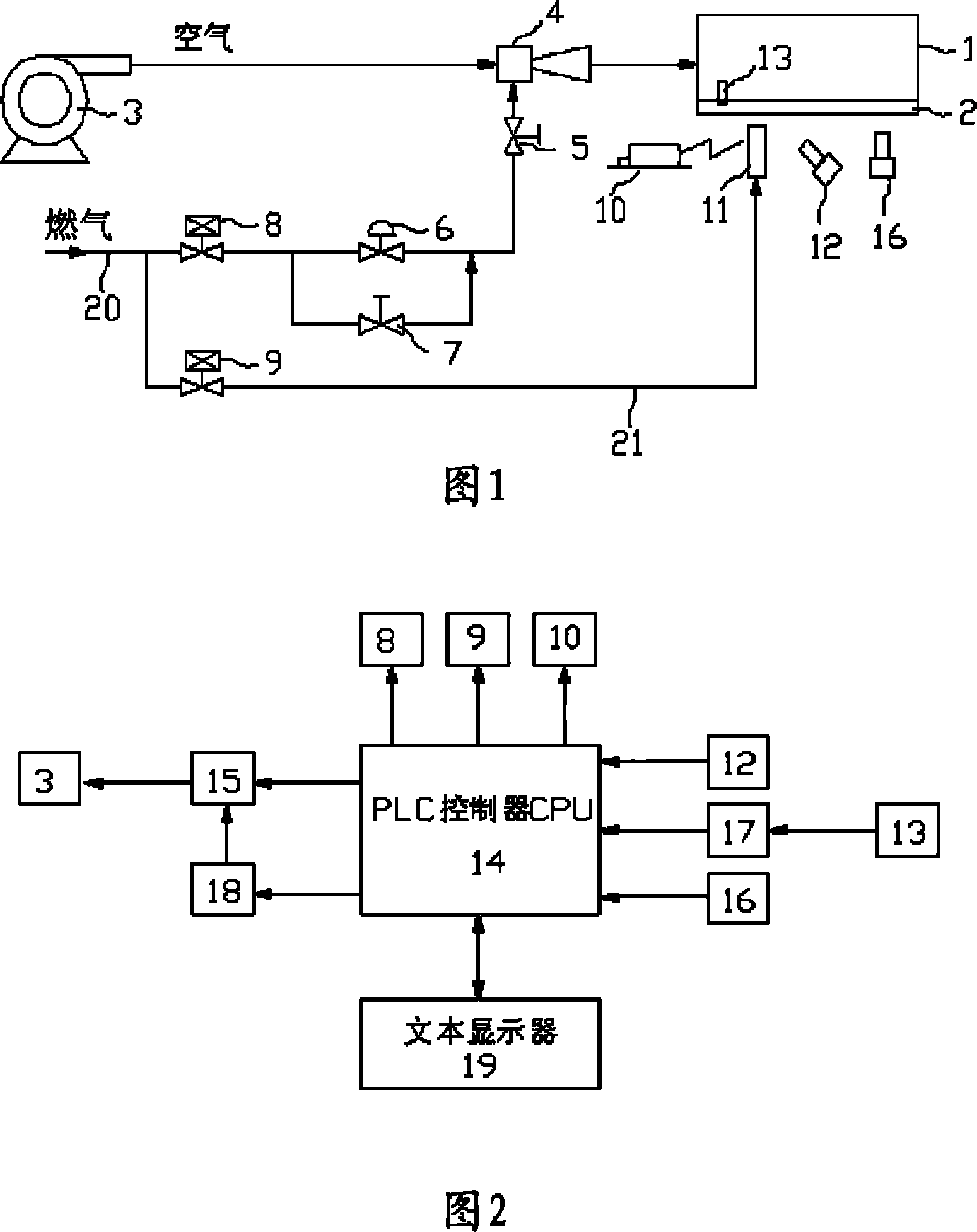
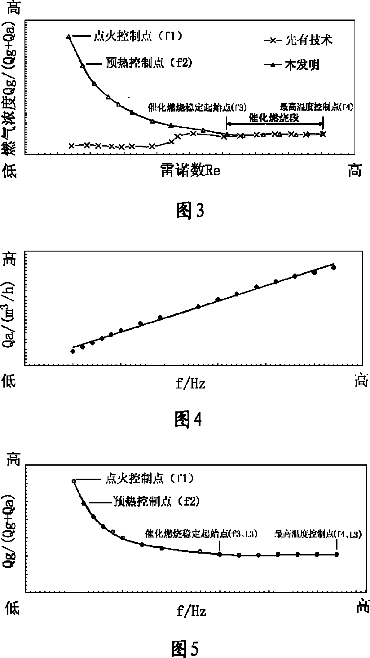
[0049] Referring to Fig. 1 and Fig. 2, the catalytic combustion control system of the present invention is composed of a fluid premix control system and a PLC control device.

[0050] The fluid premixing control system includes: a blower 3 connected in series with a Venturi mixer 4, which is used to purge the catalytic burner 1 and use the Venturi mixer 4 to introduce gas and perform uniform premixing. The output of the Venturi mixer 4 The tuyere is connected to the air inlet of the catalytic burner 1, and the throat suction port of the Venturi mixer 4 is connected to a proportional regulating valve 5, which is used to set the optimal gas premix concentration in the catalytic combustion stage. The inlet of the proportional regulating valve 5 is connected to the The outlet connection of a zero-pressure valve 6 is used to ensure that the gas entering the proportional regulating valve 5 is close to normal pressure. The inlet and outlet ends of the zero-pressure valve 6 are connect...


PUM


Abstract

The invention relates to a catalytic combustion control system, comprising fluid pre-mixed control system and PLC controller. The fluid pre-mixed control system comprises a fan connected with venturi-mixed reactor in series. Suction port at the hollow throat of venture-mixed reactor is connected with proportional regular valve and the inlet of proportional regular valve is connected with the outlet of zero-pressure valve. The zero-pressure valve is connected with needle valve in parallel. PLC controller comprises a CPU of PLC controller. By the combination technology of fluid control and PLC automatic control, in the whole fluid pre-mixed system, there is only need to control the inputting frequency of fan so as to control the outputting air quantity by the PLC control parts and different mixed concentration of gas and air demanded in the catalytic combustion process is realized. Automatic control ignition, pre-heat flaming combustion and catalytic combustion can be realized on the catalyst carrier of catalytic combustion directly. It is provided with simplified structure of catalytic combustor, decreased cubage, decreased cost, improved automaticity and control accuracy.

Description

(1) Technical field [0001] The invention relates to a catalytic combustion control system and method of a gas catalytic burner. (2) Background technology [0002] The survival and development of human beings depend on the development and utilization of energy, but the negative effects such as environmental pollution brought about by the development and utilization of energy are increasingly threatening the survival of human beings and the sustainable development of society. Such as emissions SO from ordinary combustion of fossil fuels 2 , NOx, CO 2 , CO and incompletely burned hydrocarbon UHC, causing acid rain, photochemical smog and greenhouse effect, causing serious damage to the ecology and threatening human health. To solve the problem of environmental pollution caused by combustion, it is necessary to change the traditional and backward combustion methods, improve combustion efficiency, develop new burners and combustion control technologies, and carry out comprehens...

Claims


Application Information

Patent Timeline
IPC IPC(8): F23C13/02F23N5/00
Inventor 周琦王燕京张世红
Owner BEIJING UNIVERSITY OF CIVIL ENGINEERING AND ARCHITECTURE
Learn More