Supercharge Your Innovation With Domain-Expert AI Agents!

Tapered carbon nano tube and electronic source used for the same

A carbon nanotube, electron source technology, applied in the fields of nanotechnology, nanotechnology, nanostructure manufacturing, etc., can solve the problem of limitations in increasing the voltage, and achieve the effect of reducing the loading voltage, high resolution, and small energy amplitude

Inactive Publication Date: 2007-07-04
HITACHI HIGH-TECH CORP
View PDF1 Cites 2 Cited by
  • Summary
  • Abstract
  • Description
  • Claims
  • Application Information

AI Technical Summary

Problems solved by technology

[0003] In an electron microscope, it is necessary to increase the electric field strength of the electron source in order to observe images clearly, but there is a limit to increasing the voltage

Method used


Image

  • Tapered carbon nano tube and electronic source used for the same
  • Tapered carbon nano tube and electronic source used for the same
  • Tapered carbon nano tube and electronic source used for the same

Examples


Embodiment 1

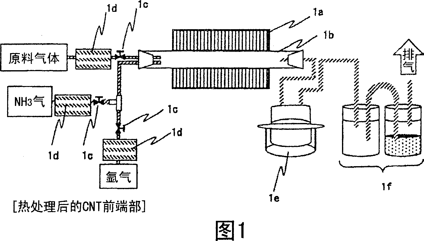
[0033] (Manufacturing method of carbon nanotubes)

[0034] Typical methods for producing carbon nanotubes include an arc discharge method, a laser rubbing method, and a vapor phase (CVD) method.

[0035] The arc discharge method is to prepare two graphite rods with a diameter of 10 mm and a length of 100 mm, and connect the end faces of each other. The above two graphite rods are arranged so that their central axes coincide with each other, leaving a gap of about 1-2mm after contact. It is also possible to apply a DC voltage in this state to discharge the arc, but there is a possibility that gas components in the air may be mixed in and contaminate the carbon nanotubes.

[0036] Therefore, the interior of the test piece chamber in which the above-mentioned graphite rod is installed is evacuated by a rotary pump to remove the above-mentioned gas components. Then, an inert gas such as He or Ar is introduced, and the pressure is adjusted to approximately atmospheric pressure. ...

Embodiment 2

[0058] Next, as shown in FIG. 3, the above-mentioned process is repeated twice and heat treatment is performed. The heat treatment temperature and time are the same as those in Example 1 above. As a result, the tip shape becomes an acute angle again. On the other hand, a part of the carbon nanotubes is cut off by multiple times of heat treatment, and the overall short carbon nanotubes can be obtained.

[0059] The crystallization of the carbon nanotubes starts centering on the above-mentioned defective portion. If there is a missing part on the carbon nanotube, it may break or the like from this part. By repeating the heat treatment twice, carbon nanotubes with a length of 10 μm or more were crystallized in 2 to 3 places, and the length sometimes became half or less.

Embodiment 3

[0061] Secondly, the effect of heat treatment on the length of carbon nanotubes is discussed. The time for maintaining the heat treatment temperature on the low temperature side in the process of Example 2 was changed, and the heat treatment was repeated twice, and the change in the length of the carbon nanotubes after the heat treatment was measured. 500 samples were checked manually, rounded to one decimal place, and classified into 1 μm, 2 μm, 3 μm, 4 μm, 5 μm, 6 μm, 7 μm, 8 μm, 9 μm, and 10 μm or more, and counted.

[0062] The results are shown in FIG. 4 . Before the heat treatment, there were many 10 μm or more, but the heat treatment increased the number of less than 10 μm. In the case of holding at 600° C. for 3 hours, many carbon nanotubes with a length of 2 μm were obtained compared with the case of 1 hour. In addition, as a result of holding at 600° C. for 6 hours, almost the same number of carbon nanotubes of 1 to 4 μm was obtained.

[0063] Therefore, when long...


PUM

PropertyMeasurementUnit
Lengthaaaaaaaaaa
Diameteraaaaaaaaaa
Lengthaaaaaaaaaa

Abstract

An electron microscope of the present invention can advance the electric field strength of electron source of the electron microscope and make the obtained pictures clear. The electron microscope has: electron ejection cathodes with carbon millimicron tubes, and the takeaway conveyor of field electron emission, with the characters of using the carbon millimicron tubes of acute angle provided with a general cone shape. Other character is that the carbon millimicron tube containing atoms 0.1-5% of at least one of boron, nitrogen, phosphor, and sulfur, makes the IG / ID ratio of Raman spectrum intensity is above 0.75 (IG: Raman scattering intensity corresponding to the stretching motion of carbon of graphite constructure, ID: Raman scattering intensity corresponding to the lattice confusion). Reducing the energy beaming of electron rays by increasing the proportion of graphite constructure.

Description

technical field [0001] The present invention relates to a carbon nanotube having a tapered front end. In addition, it also relates to the application of the carbon nanotubes to an electron source. Background technique [0002] Japanese Unexamined Patent Publication No. 2004-079223 (Patent Document 1) discloses an electron source using carbon nanotubes, and describes that an electron beam with high brightness and narrow energy width can be obtained. As for the electron source, although many studies have been carried out, the correlation between the beam shape and the electron emission position of the carbon nanotube is still unclear. In particular, it is also said that the size of carbon nanotubes is quantized in the radial direction, and the size of the above-mentioned electron emission positions has been discussed a lot in academic societies from the viewpoint of the uncertainty principle. This makes it difficult to design an electron-optical electron gun in the case of u...

Claims


Application Information

Patent Timeline
IPC IPC(8): H01J37/073H01J37/06H01J1/304C01B31/02B82B1/00B82B3/00H01J9/02H01J37/26
Inventor 林原光男藤枝正日高贵志夫
Owner HITACHI HIGH-TECH CORP
Features
  • R&D
  • Intellectual Property
  • Life Sciences
  • Materials
  • Tech Scout
  • Unparalleled Data Quality
  • Higher Quality Content
  • 60% Fewer Hallucinations
Learn More