Automated test control system and method for wavelength tunable laser

A technology for tuning lasers and automated testing, applied in the field of lasers, can solve problems such as time-consuming and labor-intensive operations, unsuitable for large-scale and large-scale fine scanning, and single system functions that are not flexible enough

Inactive Publication Date: 2007-07-11
INST OF SEMICONDUCTORS - CHINESE ACAD OF SCI
View PDF0 Cites 17 Cited by
  • Summary
  • Abstract
  • Description
  • Claims
  • Application Information

AI Technical Summary

Problems solved by technology

[0007] The purpose of the present invention is to address the traditional wavelength tunable laser testing and control methods, which are time-consuming and labor-intensive to operate, prone to errors, not suitable for large-scale and large-scale fine scanning, and the test results are not suitable for establishing a database for analysis and control, and the system function is not single enough. Flexible problem, providing an automated test and control system for wavelength tunable lasers

Method used


Image

  • Automated test control system and method for wavelength tunable laser
  • Automated test control system and method for wavelength tunable laser
  • Automated test control system and method for wavelength tunable laser

Examples


Embodiment Construction

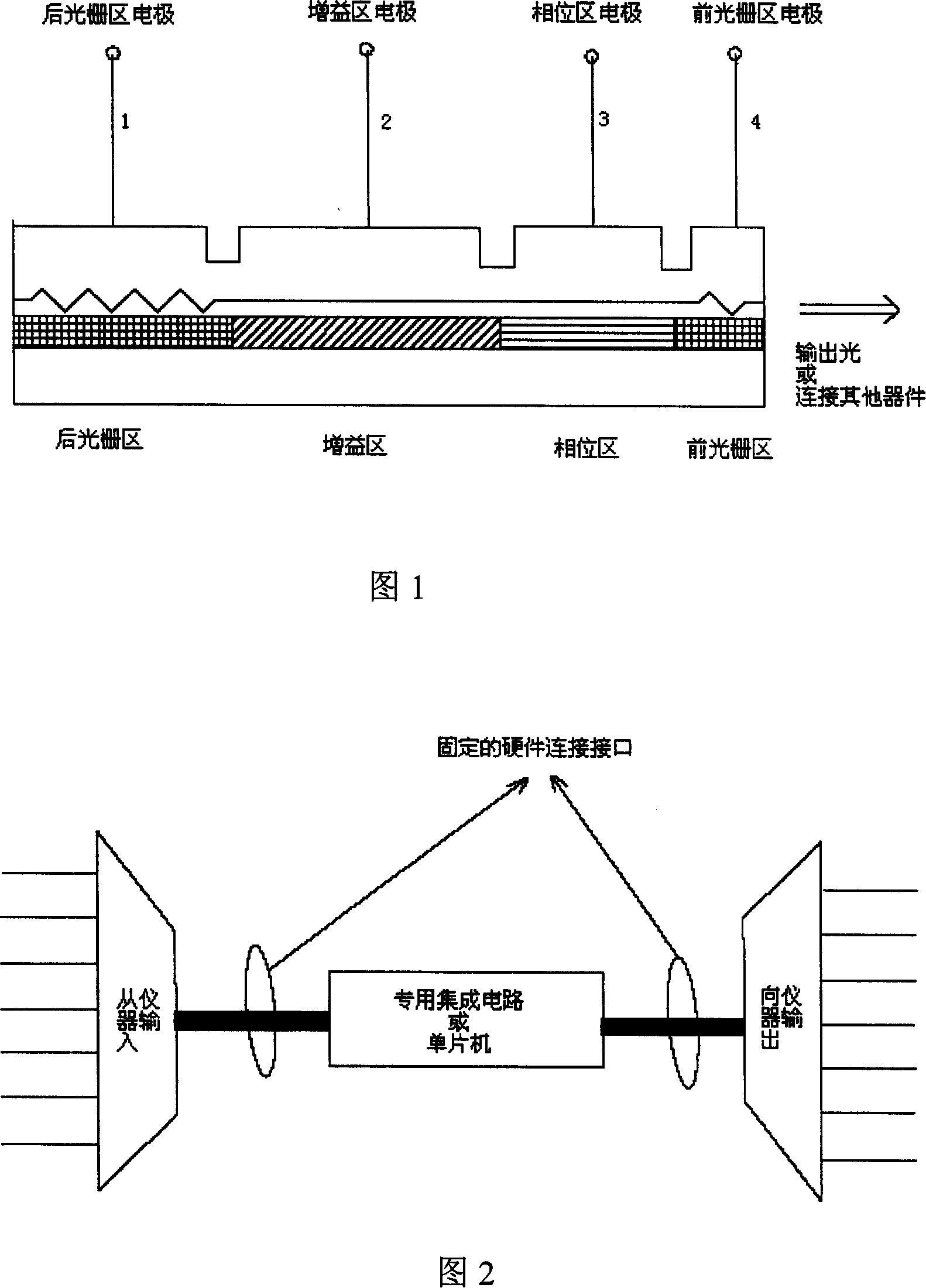
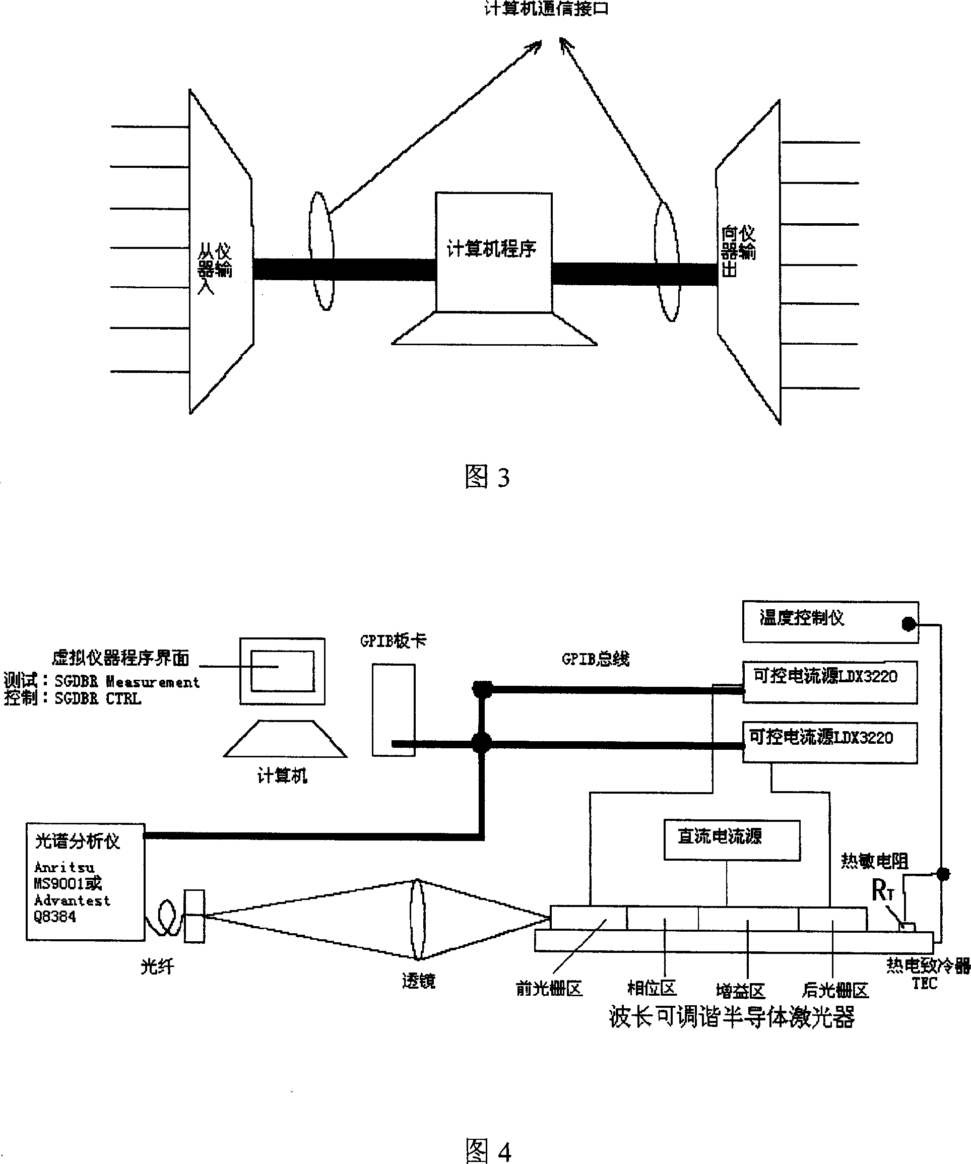
[0035] Fig. 4 is a schematic diagram of the hardware connection mode of the automatic test control system of the present invention. In the situation shown in the figure, install the GPIB board on the computer motherboard, and install the GPIB driver in the computer system. Share 3 GPIB buses for communication, connect one end of the 3 GPIB buses to the interface of the GPIB board (the GPIB interface can be superimposed and expanded), and connect the other ends to the spectrum analyzer Advantest Q8384 (or Anristsu MS9001) and 2 program-controlled current sources on the GPIB interface of IXlightwave LDX3200, and set the GPIB address to 8 on the spectrum analyzer, set the GPIB address to 1 on the program-controlled current source of the grating after driving, and set the GPIB address on the program-controlled current source of the grating before driving The address is 2. The four-segment DBR laser (SG DBR) with front and rear sampling gratings is sintered on the copper heat sink...


PUM


Abstract

The invention relates to a wavelength adjustable laser automatic inspection and control system and method. The system comprises the computer, GPIB and bus, spectral analysis, program controllable supply source, DC, temperature controller, thermoelectric cooler, laser, lens and optical fiber, with the GPIB connected to the spectral analysis and program controllable supply source, the temperature controller connected to the thermoelectric cooler which connected to the laser, light signal delivered to the spectral analysis through lens and optical fiber, and the above process is realized through instruction and data delivery with the combination of the computer, program controllable supply source, spectral analysis through the GPIB bus.

Description

technical field [0001] The invention relates to the technical field of lasers, in particular to an automatic test control system and method for a wavelength tunable laser. Background technique [0002] Wavelength tunable lasers have high rate and low chirp (in semiconductor lasers, there is a strong coupling between the carrier and photon fields. Intensity modulation will cause frequency or phase modulation at the same time. The mechanism of their interconnection The change of the carrier concentration in the active region will cause the change of the optical gain, so that the effective refractive index will change. The correlation between the intensity modulation and the frequency modulation leads to the dynamic broadening of the spectral line, which is usually achieved by the chirp of the modulation power ratio Describe this characteristic (GHz / mW). That is to say, when the semiconductor laser is subjected to direct intensity modulation, the mode frequency of the laser wil...

Claims


Application Information

Patent Timeline
Patent Type & Authority Applications(China)
IPC IPC(8): G01J3/00H01S5/00H04B10/00H04J14/02H04B10/07
Inventor 王路赵玲娟张靖俞涛王鲁峰王圩
Owner INST OF SEMICONDUCTORS - CHINESE ACAD OF SCI
Why Eureka
Try Eureka