Manufacturing method for nanoparticle

a nanoparticle and manufacturing method technology, applied in the field of nanomedicine, can solve the problems of difficult to provide precious control of particle size, complicated process, and adverse reaction, and achieve the effects of improving production efficiency, no irregularity, and uniform particle diameter

Inactive Publication Date: 2018-07-31
SHIMADZU CORP
View PDF33 Cites 0 Cited by
  • Summary
  • Abstract
  • Description
  • Claims
  • Application Information

AI Technical Summary

Benefits of technology

[0050]According to the present invention, a laminar flow of an amphiphilic block polymer having a hydrophilic block and a hydrophobic block and at least two laminar flows of water system solution are formed and nanoparticles comprising the amphiphilic block polymer is formed by making confluence as if at least two laminar flow of water system solution sandwich and enrobe and surround and bound the laminar flow of the polymer solution.
[0051]The laminar flows of water system solution sandwich the laminar flow of polymer solution from both right side and left side relative to the flow direction of the polymer solution toward downstream side from the upperstream side at the confluent section (i.e., the downstream end of the polymer solution supply flow passage). Accordingly, the laminar flow of the polymer solution flows at the center of the flow passage and the laminar flow of the water system solution flows proximate the inner periphery of the flow passage (contact area to the inside wall of the flow passage) toward the nanoparticle forming flow passage from the confluent section (the upperstream area of the nanoparticle forming flow passage). The flow rate of the laminar flow of the polymer solution increases because of running in the center of the flow passage so that the area of the liquid-liquid boundary face in between the laminar flow of the water system solution surrounding the laminar flow of the polymer solution may increase. It is considered that the self-assembly of the amphiphilic block polymer may take place mainly in the liquid-liquid boundary face. The self-assembly of the amphiphilic block polymer is enhanced by an increase of the area of the liquid-liquid boundary face at the confluent section and an increase of the flow rate of the laminar flow of the polymer solution and nanoparticles having a uniform particle diameter approximately in the range of 20-200 nm are formed (i.e., the particle distribution provides a single peak property).
[0052]According to the manufacturing method of the present invention, nanoparticles comprising the amphiphilic block polymer have a uniform particle diameter approximately in the range of 20-200 nm so that an expected EPR Effect can be obtained. Accordingly, if the nanoparticles are formulated in a labeling agent, a useful molecular probe for a molecular imaging system can be provided. Further, if the nanoparticles are formulated in a pharmaceutical substance, a useful carrier for DDS can be provided.
[0053]Further, according to the present invention, nanoparticles comprising an amphiphilic block polymer can be continuously produced. A continuous production may provide a superior production efficiency and no irregularity between batches so that nanoparticles having uniform particle diameter can be stably provided.
[0054]Further, according to the present invention, a particle diameter of a nanoparticle can be controlled by changing the flow rates of the laminar flow of the amphiphilic block polymer and the laminar flow of the water system solution.

Problems solved by technology

An anticancer agent may also seriously damage a normal tissue and accordingly, an adverse reaction is concern.
However, according to the same Patent Document, the organic solvent is removed by a dialysis process and then the particles are pulverized by a sonication process (i.e., top-down process) so that the process can be complicated.
Further, pulverization of particles by the sonication process is difficult to provide precious control of the particle size.
In addition, once prepared particles are broken down by the sonication process so that the content inside the particle might leak and the inclusion quantity of the pharmaceutical substance might be out of control.
The large particles are pulverized into micrometer size particles by using a homogenizer, i.e., top-down system, so that the inclusion quantity control of leuco dye in the microcapsule might be difficult.

Method used


Image

  • Manufacturing method for nanoparticle
  • Manufacturing method for nanoparticle
  • Manufacturing method for nanoparticle

Examples


example 1

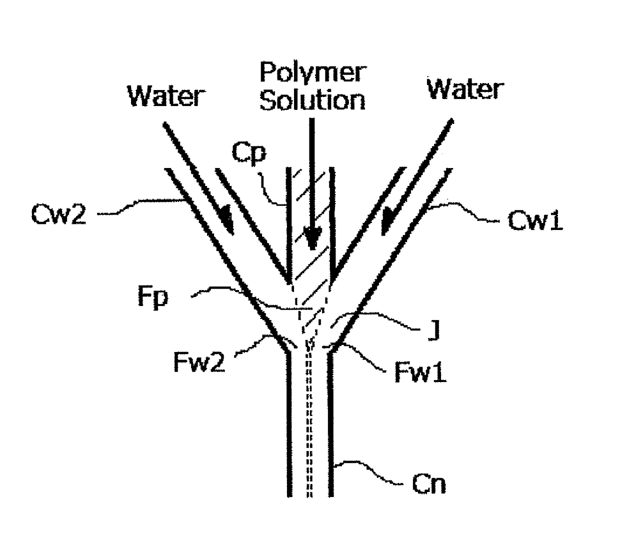
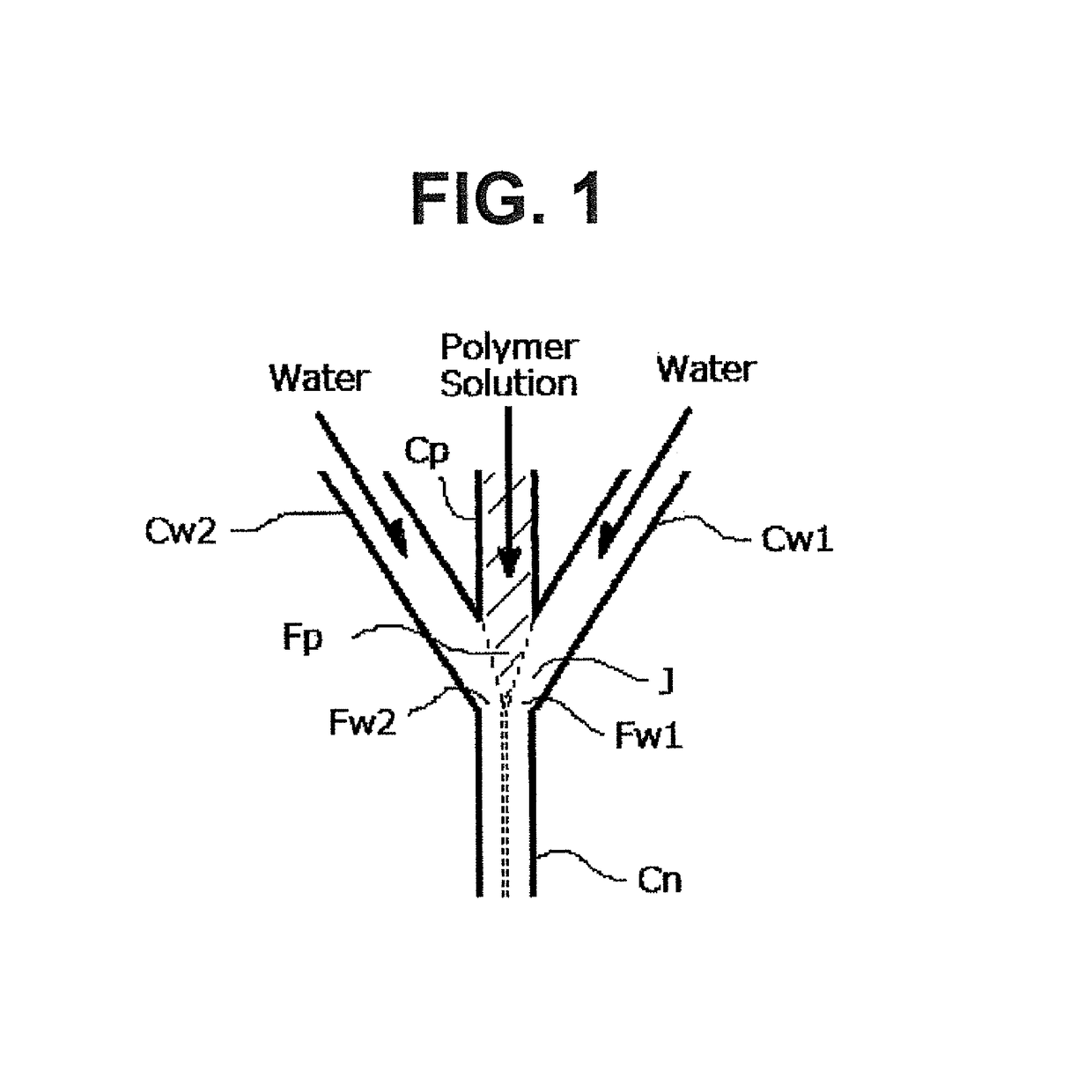
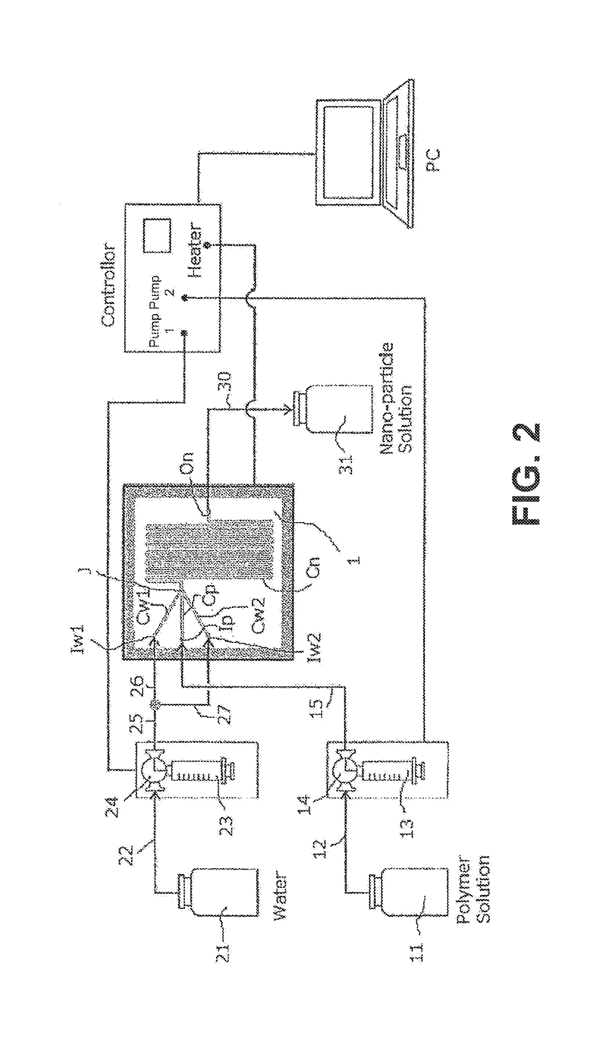
[0164]Nanoparticles were prepared from the linear type amphiphilic block polymer (PLLA39-PSar74) using apparatuses illustrated in FIG. 1-3 as follows.

[0165]Milli-Q was used for water 21. The amphiphilic block polymer (PLLA39-PSar74) was dissolved in DMF to provide the 8 mg / mL solution, and stirred at 60 for 30 min in the oil bath and then cooled down to room temperature to provide the polymer solution 11 to be used.

[0166]Referring to the apparatus in FIGs., the syringe pump 14, 24 (Hamilton PSD / 3) was used to send the solution, and two solutions of the polymer solution 11 and the water system solution 21 were induced to the micro flow cell 1 fixed to the jig through Teflon® tube 12, 15, 22, 25, 26, 27. A heater and a thermocouple are installed to the jig so that the micro flow cell can be heated. The syringe pumps 14, 24 are connected to a personal computer through a controller so that the flow rate control could be conducted by the personal computer. First, the flow passage Cn in t...

example 2

[0187]Instead of the micro flow cell 1 referring to FIG. 1-3, the micro flow cell having the same confluent structure of flow passages but double turn number of the nanoparticle formation flow passage Cn structure is employed and other than that, the same operations as Example 1 have been conducted. FIG. 7(D) is a schematic view illustrating the flow passages of the micro flow cell.

[0188]Referring to Example 2, the width of flow passage of the micro flow cell is 700 μm; the flow passage length thereof is 612 mm; the flow capacity is 29 μL; and the turn number relative to the nanoparticle formation flow passage Cn in the downstream from the confluent section J is 28. Temperature of the flow passage of the micro flow cell was 25.

[0189](a) Firstly, under FRR=9 condition, the polymer solution and water were induced to the polymer solution supply flow passage Cp and two water system solution supply flow passage Cw1, Cw2 to make 1000 μL / min of the total flow rate of the polymer solution a...


PUM

PropertyMeasurementUnit
diameteraaaaaaaaaa
polydispersity indexaaaaaaaaaa
particle diametersaaaaaaaaaa

Abstract

A manufacturing method for nanoparticles including an amphiphilic block polymer having a uniform particle diameters has steps of forming a laminar flow of polymer solution by inducing a solution comprising an amphiphilic block polymer having a hydrophilic block and a hydrophobic block in an organic solvent into a polymer solution supply flow passage, a step of forming at least two laminar flows of a water system solution by inducing the water system solution to at least two water system solution supply passages, and a step of forming nanoparticles comprising the amphiphilic block polymer by making a confluence as if at least two laminar flows of water system solution sandwich the laminar flow of the polymer solution.

Description

CROSS REFERENCE TO RELATED APPLICATION[0001]This application relates to, but does not claim priority from, JP App. Ser. No. 2013-28491 filed Feb. 17, 2013, the entire contents of which are incorporated herein by reference.FIGURE SELECTED FOR PUBLICATION[0002]FIG. 1BACKGROUND OF THE INVENTION[0003]Field of the Invention[0004]The present invention relates to supermolecular chemistry, medicine, technology and pharmacology alliance area and nano-medicine. The present invention further relates to a manufacturing method for a nanoparticle comprising an amphiphilic block polymer, and further specifically relates to the nanopolymer comprising the amphiphilic block polymer using a novel combinatorial structure made from polymer solution and an aqueous solution. Even more particularly, the present invention provides for a continuous manufacture method and system of nanoparticles having a homogeneous particle diameter comprising a block polymer having a superior biocompatibility. In addition, ...

Claims


Application Information

Patent Timeline
Patent Type & Authority Patents(United States)
IPC IPC(8): C08J3/12A61K9/16B01J19/00B01F13/00B82Y40/00B01J2/06
CPCC08J3/12B01F13/0062B82Y40/00B01J19/0093B01J2/06C08J2367/04C08J2371/02B01F33/3011
Inventor KAWABE, TAKASHIOZEKI, ELICHI
Owner SHIMADZU CORP
Why Eureka
Try Eureka