
Intermodulation sensor platform based on mechanical resonator

a mechanical resonator and intermodulation technology, applied in the direction of instruments, resonant frequency, measurement devices, etc., can solve the problems of power-limited read-out distance of digital sensors, limited application possibilities of piezoelectric materials for sensing elements, and limited signal-to-noise ratio of analog sensors, etc., to achieve poor electro-acoustic transformation efficiency, read-out distance, and power consumption. increased

Inactive Publication Date: 2018-12-04
TEKNOLOGIAN TUTKIMUSKESKUS VTT
View PDF14 Cites 7 Cited by
  • Summary
  • Abstract
  • Description
  • Claims
  • Application Information

AI Technical Summary

Benefits of technology

The platform achieves higher quality factor and equivalent inductance for a given self-resonant frequency, enabling larger read-out distances and smaller frequency offsets, thus enhancing the sensor's operational range and compliance with frequency regulations, while allowing for the monitoring of virtually any quantity.

Problems solved by technology

In addition, the read-out distance of digital sensors is often power-limited while that of analog sensors is limited by the signal-to-noise-ratio.
The need to use a piezoelectric material for a sensing element limits possible applications.
In addition, the smallest line-width of the IDT structure limits the highest operation frequency of a SAW tag to a few GHz.
These sensors require a near-field coupling to the reader, which limits their read-out distance to a few centimeters.
Another hindrance is that their resonance may be affected by a proximity to conductive or dielectric objects.
There are some drawbacks with the previously published sensors utilizing the intermodulation communication principle.
First, the sensor presented in uses a MEMS element simultaneously for mixing and sensing, which implies that the MEMS needs to be compromised between the two functions.
A hindrance of this design, however, is that an inductor is used to obtain a resonance at a low frequency.
A self-resonance frequency of the inductor limits the smallest achievable frequency offset and the quality factor of the inductor limits the conversion efficiency and thus the read-out distance.
Due to these reasons, the frequency offset needs to be relatively large and the read-out distance is limited.
Large frequency offset impedes the compliance with frequency regulations.

Method used


Image

  • Intermodulation sensor platform based on mechanical resonator
  • Intermodulation sensor platform based on mechanical resonator
  • Intermodulation sensor platform based on mechanical resonator

Examples


Embodiment Construction

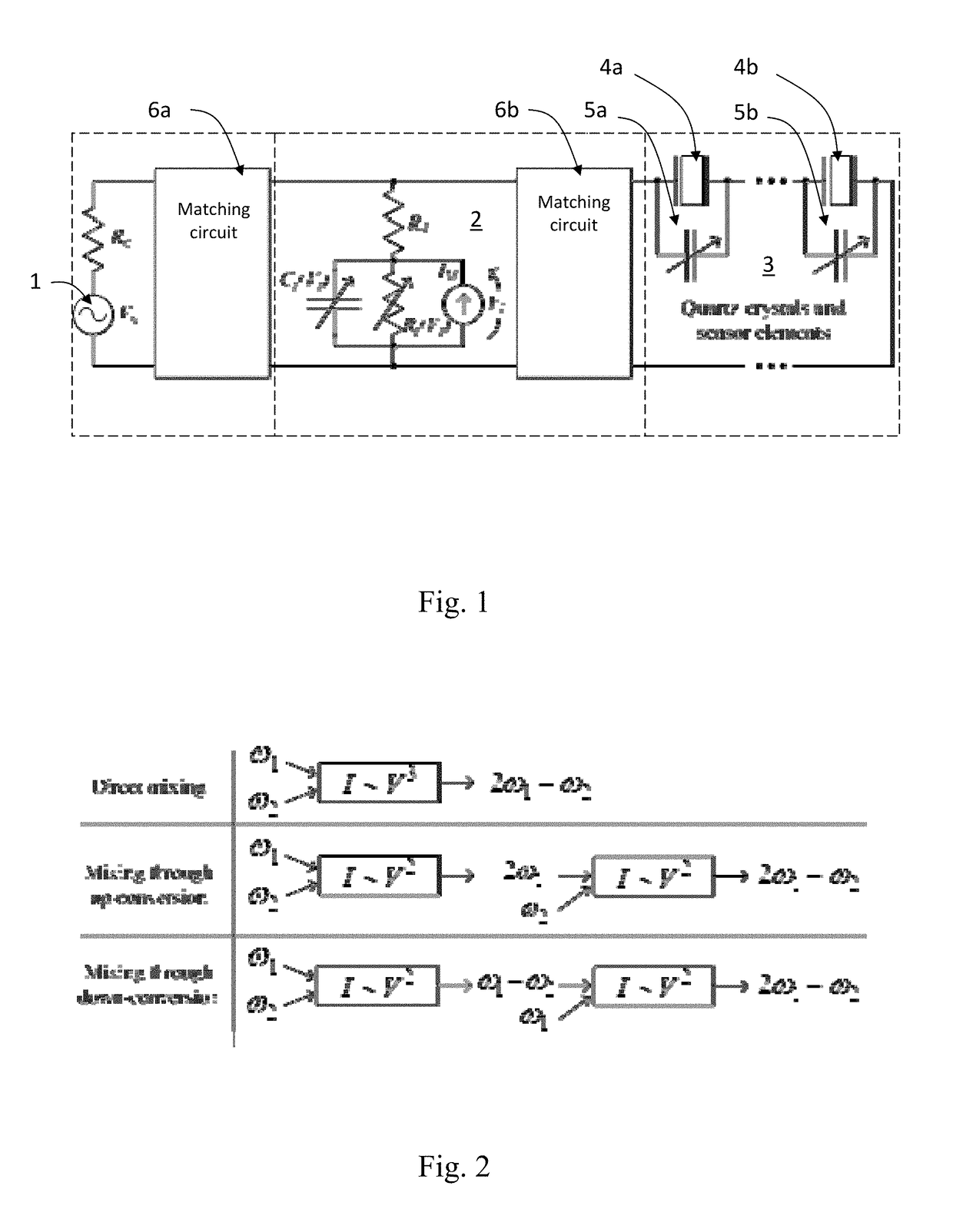
[0031]In the intermodulation communication principle, a sensor replies at an intermodulation frequency when it is actuated by a reader device with two sinusoids. The sensor is designed such, that its intermodulation response (that is, the ratio between the voltage at the intermodulation frequency and at a fundamental frequency across the antenna) is affected by a sensor element.

[0032]The sensor comprises, for example, an antenna 1, a mixing element 2, and a low-frequency resonant circuit 3. The mixing element 2 may be a passive mixer. An example of a mixing element 2 is a Schottky diode as shown in FIG. 1. The mixer generates an excitation at the difference frequency, which is applied to the low-frequency resonant circuit 3. The low-frequency resonant circuit 3 comprises a capacitive, resistive, or inductive sensor element.

[0033]An example of the electrical equivalent circuit of the sensor is shown in FIG. 1. The antenna 1 is represented as a voltage source, the Schottky diode is us...


PUM


Abstract

The present invention related to a new passive wireless sensor platform which is based on the intermodulation communication principle. The platform may utilize a quartz crystal or other mechanical resonator. Additionally, the platform allows for a narrow bandwidth and / or ID-code of a sensor. Certain embodiments enable high frequencies and large read-out distances. It facilitates a generic sensor element and can thus be used to monitor virtually any quantity. Additionally, it offers a means to realize a wireless passive sensor using MEMS sensor technology.

Description

FIELD OF INVENTION[0001]The present invention related to a new passive wireless sensor platform which is based on the intermodulation communication principle. The platform may utilize a quartz crystal or other mechanical resonator. Additionally, the platform allows for a narrow bandwidth and / or ID-code of a sensor.BACKGROUND OF THE INVENTION[0002]Wireless passive sensors do not require any power source for operation other than the interrogation signal from the reader. The advantages of passive sensors over active and semi-passive sensors are that they are potentially more inexpensive and their operation conditions or life-time are not limited by the power source, such as a battery or energy harvester.[0003]Passive wireless sensors can be divided into digital and analog sensors. The IC (Integrated Circuit)-based RFID (Radio Frequency Identification) utilizes digital logic which offers highly sophisticated features such as anti-collision protocols and non-volatile memory. The IC RFID ...

Claims


Application Information

Patent Timeline
Patent Type & Authority Patents(United States)
IPC IPC(8): G01H13/00H04B1/28
CPCH04B1/28G01H13/00
Inventor VIIKARI, VILLESEPPA, HEIKKI
Owner TEKNOLOGIAN TUTKIMUSKESKUS VTT
Learn More