Substrate processing apparatus

a processing apparatus and substrate technology, applied in semiconductor/solid-state device testing/measurement, instruments, material analysis, etc., can solve the problems of measurement errors, concentration measurement cannot be carried out in real time, etc., and achieve the effect of reducing the amount of etching of silicon nitride film, good precision and high precision

Active Publication Date: 2018-12-11
KURASHIKI BOSEKI KK +1
View PDF19 Cites 0 Cited by
  • Summary
  • Abstract
  • Description
  • Claims
  • Application Information

AI Technical Summary

Benefits of technology

[0018]Therefore, an object of the present invention is to provide a substrate processing apparatus that can perform independent concentration control because the concentration of the processing liquid can be directly sensed and, moreover, processing of the substrate with a chemical agent can be carried out with a good precision because measurement errors caused by temperature change of the lenses are hardly generated.
[0033]According to the substrate processing apparatus of the present invention, the concentration sensing means directly senses the concentration of the processing liquid by measuring the absorbance characteristics of the processing liquid, so that an independent concentration control can be made with little influence given from the temperature of the processing liquid. Further, since the concentration sensing means includes a cooling mechanism that cools the lenses, measurement errors caused by temperature change of the lenses are hardly generated, whereby the concentration of the processing liquid can be sensed with a higher precision, so that the processing of the substrate with a chemical agent can be carried out with a good precision. Also, for example, even when the temperature of the processing liquid lowers by immersion of a substrate wafer, replenishment with water or stoppage for maintaining the concentration of the processing liquid can be made and, as a result, the etching of the silicon nitride film will be stabilized. Also, according to the present invention, the ratio of mixing the chemical agent with the diluent can be freely controlled within a range above or equal to the boiling point concentration of the chemical agent, so that, for example, by setting the concentration of the phosphoric acid solution to be higher than the boiling point concentration, the amount of etching the silicon nitride film can be reduced and the amount of etching the silicon oxide film can be increased.
[0034]In the present invention, it is preferable to further comprise a first lens holding section that holds the first lens and a second lens holding section that holds the second lens, wherein the cooling mechanism performs the cooling via at least one of the first lens holding section and the second lens holding section. By this feature, the lenses can be indirectly cooled via the lens holding sections, so that the efficiency and the uniformity of cooling can be enhanced. Also, since the cooling mechanism is provided in the first and second lens holding sections, not only the lenses but also the first and second lens holding sections themselves can be cooled. As a result thereof, the deformation and dilatation of the lens holding sections by heat can be prevented, whereby the position of holding the lenses can be maintained to be a constant position, so that the phosphoric acid concentration can be measured at a high precision.
[0035]It is preferable that the cooling mechanism comprises a flow path disposed in the first lens holding section or the second lens holding section and means for supplying a cooling fluid to the flow path. By this feature, the lenses can be cooled efficiently by the cooling fluid supplied to the lens holding sections.
[0036]In the embodiment, it is preferable that the flow path is disposed in the first lens holding section or the second lens holding section to surround all or a part of peripheries of the first lens or the second lens. By this feature, the cooling fluid can be supplied to the part of the lens holding sections that surround the lenses, so that the efficiency and the uniformity of cooling can be enhanced to a greater extent.
[0037]Also, it is preferable to further comprise a base section that supports the first lens holding section and the second lens holding section, wherein a cooling mechanism is provided in the base section. By cooling the base section, the influence of deformation caused by heat of the base section can be prevented, and also the influence of heat directly transmitted to the lens holding sections via the base section from the flowcell section can be reduced, so that the concentration measurement can be made at a higher precision.

Problems solved by technology

However, in the case of the concentration measuring method disclosed in JP-A-2009-58306, a step of gradually lowering the temperature of the aqueous solution will be needed, so that the concentration measurement could not be carried out in real time though the method is an optical sensing method.
However, according to the studies made by the present inventors, it has been found out that, in sensing the concentration of a processing liquid by an optical sensing method in a substrate processing apparatus that performs etching with a high-temperature phosphoric acid solution, the lenses disposed in the neighborhood undergo temperature change by radiation heat from the measurement cell, so that measurement errors occur by being affected therefrom.
Here, the fact that, in a concentration measuring apparatus using an optical sensing method, the lenses disposed in the neighborhood undergo temperature change by radiation heat from the measurement cell and measurement errors occur by being affected therefrom, and the countermeasures against this have not been known up till now.

Method used


Image

  • Substrate processing apparatus
  • Substrate processing apparatus
  • Substrate processing apparatus

Examples


experiment example 1 (

Influence of Optical Characteristics Change by Temperature Rise of the Lens)

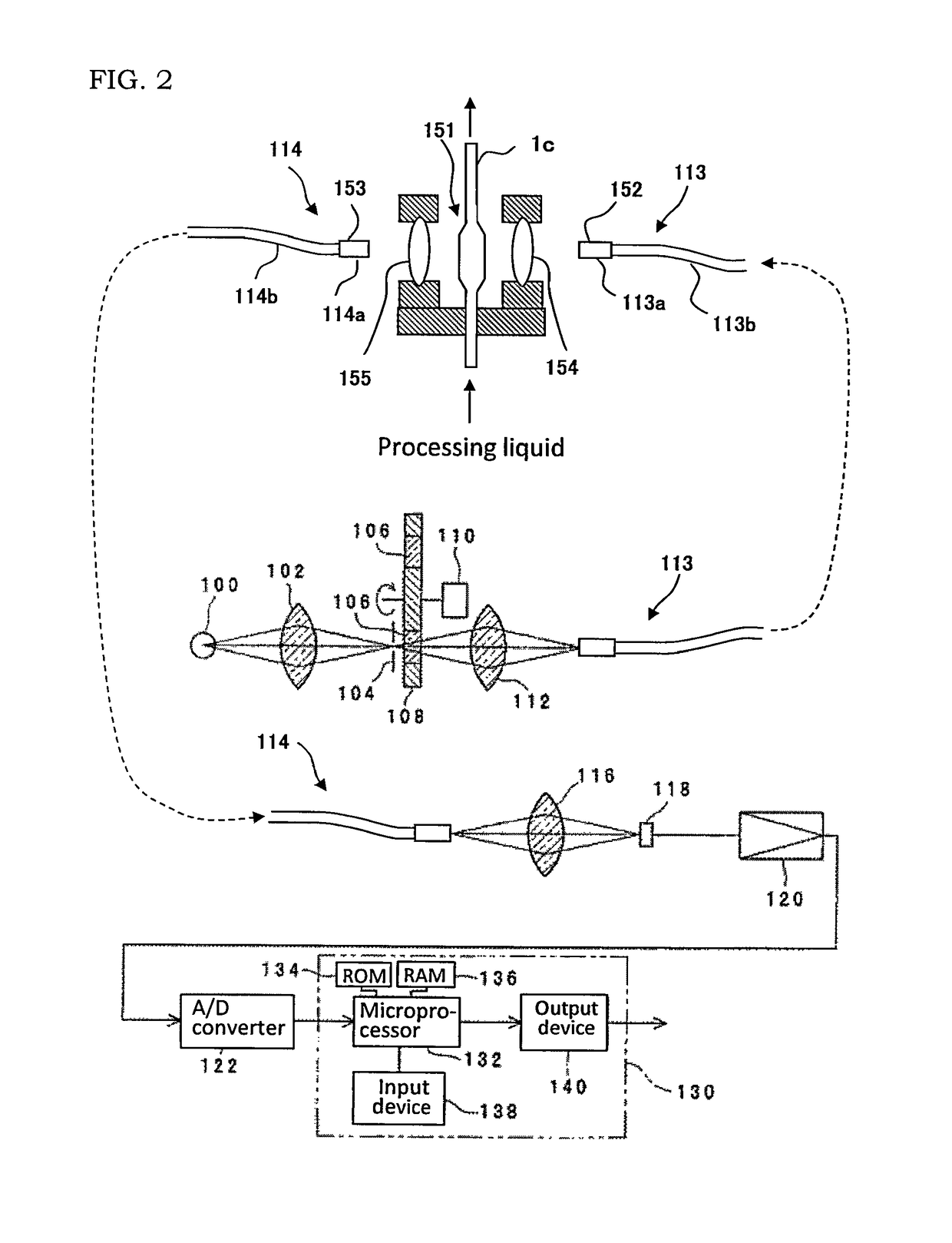
[0111]With use of an experiment apparatus having an optical system shown in FIG. 6, how the measurement value of zero % concentration changes in accordance with the change in the lens temperature from 25° C. in a thermostatic chamber set at 25° C. was examined without using a cell for measurement. Adjustment of the optical axis of the optical system was made using a laser so that the axial shift would be 1 mm or less at a point distant by 2 m. At the time of measurement, by changing the temperature of warm water supplied (flow rate of 1.9 L / minute) to the flow path each by 5° C. from 30° C. to 50° C., the temperature of the lens at that time was measured, and also the change in the concentration (%) corresponding to each temperature was measured using an apparatus shown in FIG. 2. The result thereof is shown in FIG. 7.

[0112]As will be clear from this result, it has been confirmed that, when the lens temperat...

experiment example 2 (

Influence of Optical Axis Change by Temperature Rise of the Lens Holding Section)

[0113]By using an experiment apparatus being capable of constructing an optical system shown in FIG. 6 and further having a fixed position adjustment section (XYZ stage) relative to one of the lens holding sections, how the measurement value of zero % concentration changes in accordance with the change in temperature from 25° C. in a thermostatic chamber set at 25° C. was examined without using a cell for measurement. Adjustment of the optical axis of the optical system was made using a laser so that the axial shift at the basis position would be 1 mm or less at a point distant by 2 m. At the time of measurement, the fixed position was adjusted each in the horizontal direction X (−0.2 mm to 0.2 mm) perpendicular to the optical axis, in the height direction Y (−0.2 mm to 0.2 mm), and in the horizontal direction Z (−1.0 mm to 12.5 mm parallel to the optical axis from the standard position (position at whi...

experiment example 3 (

Influence of Cooling by Cooling Water)

[0116]By using an experiment apparatus having an optical system shown in FIG. 6 and using a quartz cell for measurement, how the measurement value of concentration changes by presence or absence of cooling water was examined while allowing an aqueous solution of phosphoric acid having a temperature of 120° C. and a concentration of 67.80 wt % to flow (flow rate of 1.5 L / minute). Adjustment of the optical axis of the optical system was made using a laser so that the axial shift would be 1 mm or less at a point distant by 2 m. At the time of measurement, the temperature of each section was continuously measured, and also the change in the concentration (%) at each time was measured using an apparatus shown in FIG. 2. The result thereof is shown in FIG. 9. Here, the dots in the Figure show measurement values of concentration. As the temperature of each section, the measurement values in the inside (cell side) and on the outside (optical fiber side)...


PUM

PropertyMeasurementUnit
temperatureaaaaaaaaaa

Abstract

A substrate processing apparatus that performs processing by immersing a substrate into a processing liquid obtained by mixing phosphoric acid with a diluent includes a concentration sensing means for sensing the concentration of the processing liquid by measuring the absorbance characteristics of the processing liquid. The concentration sensing means includes a light-transmitting section that introduces the processing liquid into the inside to let the processing liquid pass therethrough, a light-emitting section that radiates light having a predetermined wavelength to the light-transmitting section, a light-receiving section that receives the light therefrom via the light-transmitting section, a first lens that condenses the light emitted from the light-emitting section to the light-transmitting section, a second lens that condenses the light that has passed through the light-transmitting section to the light-receiving section, and a cooling mechanism that cools at least one of these.

Description

CROSS-REFERENCE TO RELATED APPLICATIONS[0001]This application claims priority to Japanese Patent Application No. 2011-189159 filed on Aug. 31, 2011, the disclosure of which, including the specification, the drawings, and the claims, is hereby incorporated by reference in its entirety.BACKGROUND OF THE INVENTION[0002]Field of the Invention[0003]The present invention relates to a substrate processing apparatus that performs processing of a substrate such as a semiconductor wafer, a glass substrate for a liquid crystal display device, or a glass substrate for a photomask (hereafter simply referred to as “substrate”) with a processing liquid and, in particular, is useful as a technique of performing concentration control while sensing the concentration of the processing liquid at a high precision when immersing and processing the substrate in the processing liquid that has been heated to a high temperature.[0004]Description of the Related Art[0005]Conventionally, as a substrate processi...

Claims


Application Information

Patent Timeline
Patent Type & Authority Patents(United States)
IPC IPC(8): H01L21/67H01L21/311G01N21/3577
CPCH01L21/67086G01N21/3577H01L21/67253H01L21/67248H01L21/31111H01L21/306H01L22/00
Inventor HIGASHI, NOBORUHIRAKI, SATORUKIYOSE, HIROMISATO, HIDEAKIKOMIYA, HIROSHI
Owner KURASHIKI BOSEKI KK
Why Eureka
Try Eureka