System and methods for improved sheet metal cutting with improved sharper corners cutting technique

a cutting technique and cutting system technology, applied in the field of system and methods for improving plasma cutting, can solve problems such as gaps and overlaps, and achieve the effect of not wasting material

Active Publication Date: 2019-04-16
WORTH PFAFF INNOVATIONS
View PDF9 Cites 4 Cited by
  • Summary
  • Abstract
  • Description
  • Claims
  • Application Information

AI Technical Summary

Benefits of technology

[0012]The present invention further discloses an integrated CAD / CAM / CNC system in which full knowledge of the dynamics of the entire system can be utilized to precisely calculate the length of a corner loop to control the acceleration / deceleration zone outside of the part to be cut to generate sharp corners. The system can utilize formulas, for example, for stopping distance, and other calculations, which can be used to minimize the length of a corner loop, thus maximizing material usage while maintaining good cut quality.
[0015]The present invention also discloses a three dimensional display system when a user of a CNC machine is using the machine in manual or manual hand wheel mode. The manual hand wheel simulation system provides a real-time display of the movement of the process displaying the X, Y and Z position and can also show a three dimensional display of the part being machined even if it is not actually being cut. This provides for information to the user and also can be used as a teaching tool without wasting material.

Problems solved by technology

These gaps and overlaps can become a problem when trying to make a proper toolpath, because a CAM program requires a clean, closed shape to make a toolpath.

Method used


Image

  • System and methods for improved sheet metal cutting with improved sharper corners cutting technique
  • System and methods for improved sheet metal cutting with improved sharper corners cutting technique
  • System and methods for improved sheet metal cutting with improved sharper corners cutting technique

Examples


Embodiment Construction

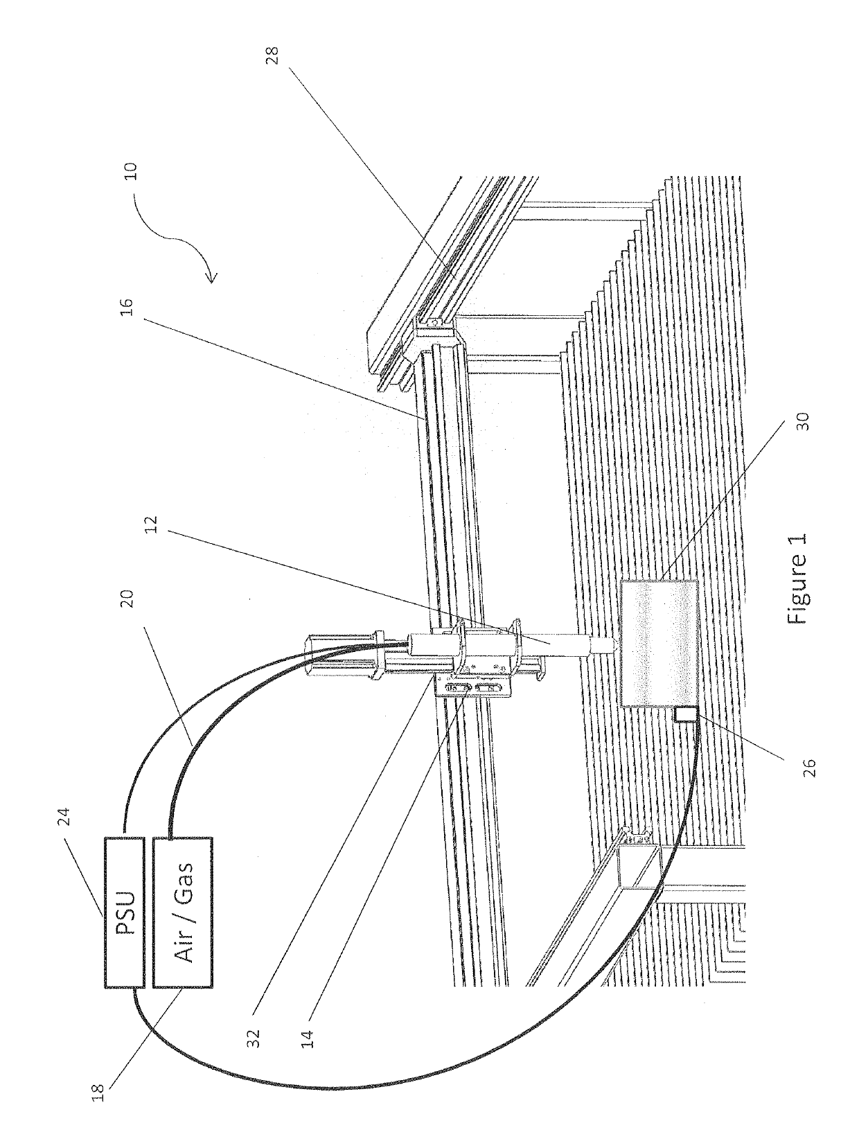
[0054]In general, plasma cutting is performed by projecting an inert gas or compressed air from a plasma torch nozzle towards the surface of the material to be cut, and driving an electrical current through the gas by applying a voltage between the cutter and the material to form a plasma within the projected gas. The plasma is hot enough that it can be used to cut a variety of different materials.

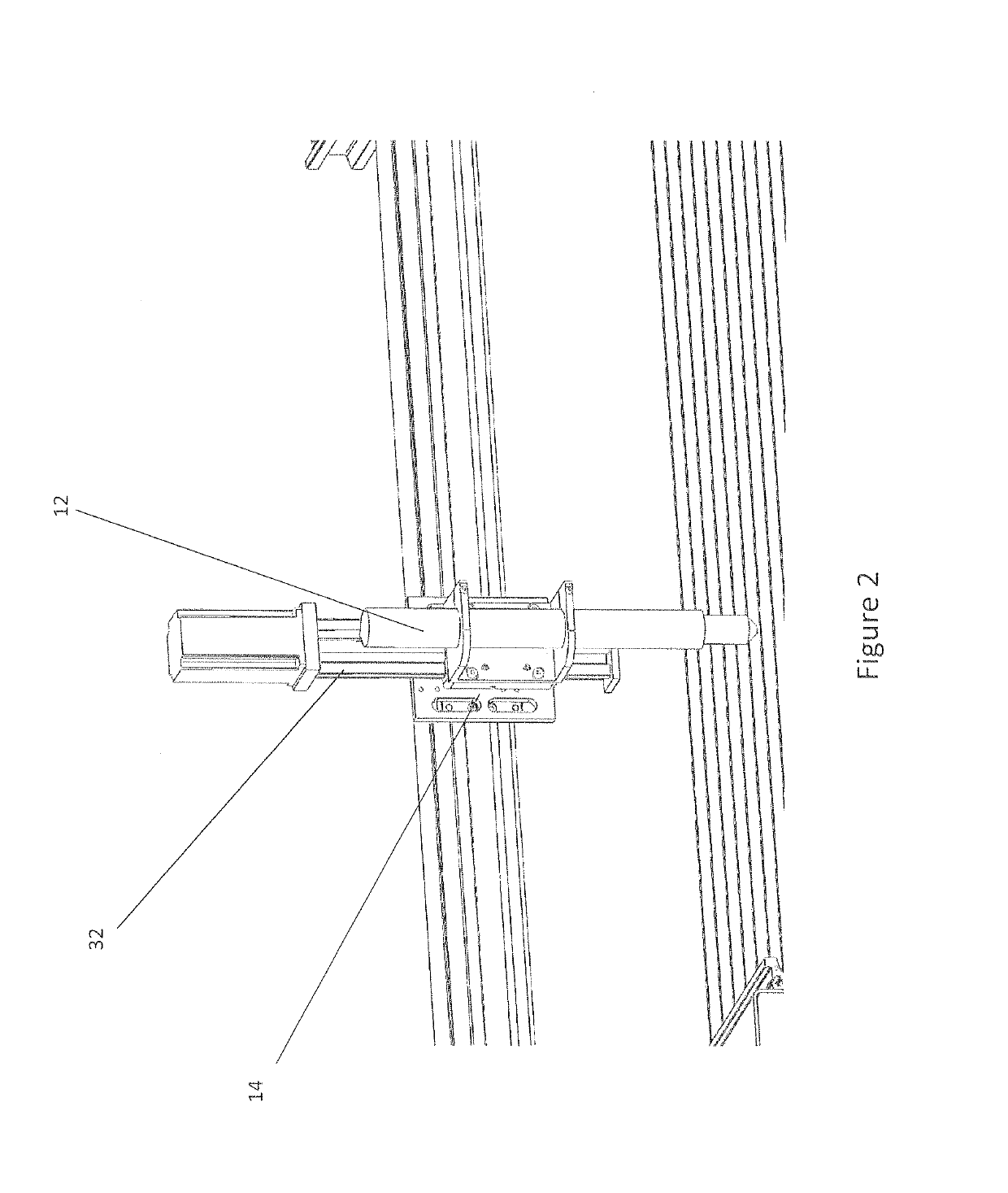
[0055]FIG. 1 shows an exemplary plasma cutting system 10 for cutting different types of materials as described herein. The plasma cutting system 10 includes a plasma torch 12 along with the torch carriage assembly 14, gantry 16, which allows the torch carriage assembly 14 to move along an axis, a rail system 28 for moving the gantry 16 and torch carriage assembly 14 along a different axis, an air / gas supply 18, a flexible conduit 20 for air or gas delivery to the plasma torch 12, a power supply 24, and a ground clamp 26, all for use in cutting material 30 using the plasma cutting system 10...


PUM

PropertyMeasurementUnit
voltageaaaaaaaaaa
voltageaaaaaaaaaa
voltageaaaaaaaaaa

Abstract

A plasma cutting system for measuring or monitoring the voltage between a plasma torch and the material being cut to determine a voltage or voltage signature and comparing that measurement against predetermined values to indicate that an initial pierce of the material is complete, and based on the measurement, moving the torch or the material to a different location for additional cutting. The system further provides a Fix Drawing Tool, which will automatically detect and fix gaps or overlaps in a drawing that are very difficult to find visually. These gaps and overlaps become a problem when trying to make a proper toolpath because a CAM program requires a clean, closed shape. The system also provides a Dynamic Corner Looping system, which automatically adjusts with the feed-rate and accelerations of the toolpath and plasma machine, eliminates unwanted dross, sharpens corners and minimizes material loss. A pendant tethering system is also disclosed for managing control of a CNC machine remotely. Additional disclosed functionality includes a data collection system, a manual hand wheel with 3D simulation and a multiple fabrication head management system.

Description

FIELD OF THE INVENTION[0001]The present application is a continuation of and claims priority to U.S. Provisional Patent Application Ser. No. 62 / 252,272, filed Nov. 6, 2015, and entitled “SYSTEM AND METHODS FOR IMPROVED PLASMA CUTTING”. This application is hereby incorporated by reference in its entirety.BACKGROUND OF THE INVENTION[0002]It is known to use a plasma cutter to cut a material, such as, for example only, steel, sheet metal, aluminum, and the like. In general, plasma cutting is performed by projecting an inert gas or compressed air from a source through a plasma torch nozzle towards the surface of the material to be cut, and simultaneously driving an electrical current through the gas or air by applying a voltage between the cutter and the material to form a plasma within the projected gas or air. The generated plasma is hot enough that it can be used to cut a variety of different materials. Other sheet metal cutting methods include laser cutting, waterjet cutting and oxy-...

Claims


Application Information

Patent Timeline
Patent Type & Authority Patents(United States)
IPC IPC(8): G05B19/41B23K10/00G05B19/19
CPCB23K10/006G05B19/19G05B2219/49111B23K10/00B23K37/0235B23K26/0626B23K26/0876B23K26/38G05B19/4097G05B2219/43129G05B2219/35009Y02P80/30Y02P90/02
Inventor PFAFF, ERICWORTH, RONALD K.
Owner WORTH PFAFF INNOVATIONS
Why Eureka
Try Eureka