
Test device for defect inspection

a technology of defect inspection and test device, which is applied in the direction of electronic circuit testing, electrical equipment, electric discharge tubes, etc., can solve the problems of affecting device yield, non-systematic defects, random particle defects, etc., and achieves the effect of increasing inspection throughput, reducing the risk of failure, and improving the accuracy of defect captur

Active Publication Date: 2019-04-30
ASML NETHERLANDS BV
View PDF8 Cites 3 Cited by
  • Summary
  • Abstract
  • Description
  • Claims
  • Application Information

AI Technical Summary

Benefits of technology

This approach enables efficient identification of open / short circuit defects with increased throughput and accuracy by using VC mode inspection and identical fabrication processes, ensuring precise defect capture without the need for detailed scanning of fine patterns.

Problems solved by technology

Undoubtedly, compared to any other technology or knowledge, semiconductor devices not only impact nowadays society but also influence our daily life.
Defects are inevitably generated in the semiconductor process, which will greatly impact device performance, even failure.
Device yield is thus impacted and cost is raised.
On the other hand, the non-systematic defects, random particle defects, are random residues left in wafers.
More specifically, systematic defects can be classified as reticle errors in alignment or machine offset, process mistakes incurred by recipes or materials, prober damages in wafer probing, scratches on wafer surface, and wafer edge effect of topography incurred from non-uniformity of PR coating or thermal stress.
Defects incurred in lithographic process include PR residue defects due to PR deteriorated or impurity, peeling defects, bridge defects, bubble defects, and dummy pattern missing defects due to pattern shift.
Defects incurred in etching process include etching residue defects, over-etching defects and open circuit defect.
Defects incurred in CMP process include slurry residue defects, dishing defects and erosion defects due to variant polishing rates, scratched due to polishing.
Further, when process nodes continue shrinking, new materials and processes will be introduced to inevitably incur new type defects.
Thinning defects are another inevitably incurred in the process node shrinking.
Such hidden, crucial defects are too hard to be analyzed and eliminated.
For the non-systematic defects are mainly random particles defect incurred from particles in air randomly fallen on the wafer, which are not easy to be identified and resolved.
Unimportant small defects in previous now become critical therefore.
It is a challenge to identify such small defects by using conventional optical inspection tool and a new tool is necessary.
The review SEM is designed to known, identified defects or suspects of defect, so scan duration is long enough to analyze or review defects, and hence it can't process inspection.
Furthermore, in lithographic process, some particular patterns may have great possibility to incur defects, but won't incur them each time.
The defects generated by these particular patterns even can't be modified through recipe tuning or modifying reticle directly.
Moreover, in order to obtain exact dimension, resolution is very critical, and thus low beam current must be applied.
The cross-contamination is caused by the ion implantation which produces unexpected dopants in the wafer, and the concentration of the unexpected dopants is usually so high that the electricity of a wafer becomes abnormal.
In conclusion, both the two prior arts aforementioned can only provide electrical characteristic results; that is, the tested results only come from the electrically contact between the four-point probe and the test circuit configured in the scribe line within a die.
However, since the fabrication process of the test circuit is different from that of the die, the test result of the test circuit configured in the scribe line may be actually different from that of the die itself.
Thus, the test result is not so precise enough and is unreliable as well.

Method used


Image

  • Test device for defect inspection
  • Test device for defect inspection
  • Test device for defect inspection

Examples


Embodiment Construction

[0055]Various example embodiments of the present invention will now be described more fully with reference to the accompanying drawings in which some example embodiments of the invention are shown. In the drawings, the thicknesses of layers and regions may be exaggerated for clarity.

[0056]Detailed illustrative embodiments of the present invention are disclosed herein. However, specific structural and functional details disclosed herein are merely representative for purposes of describing example embodiments of the present invention. This invention, however, may be embodied in many alternate forms and should not be construed as limited to only the embodiments set forth herein.

[0057]Accordingly, while example embodiments of the invention are capable of various modifications and alternative forms, embodiments thereof are shown by way of example in the drawings and will herein be described in detail. It should be understood, however, that there is no intent to limit example embodiments ...


PUM


Abstract

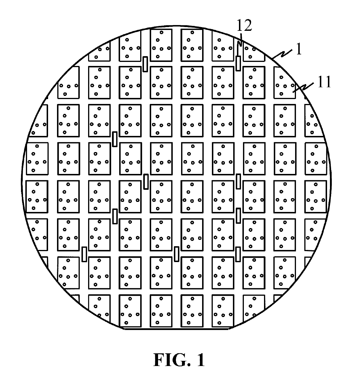
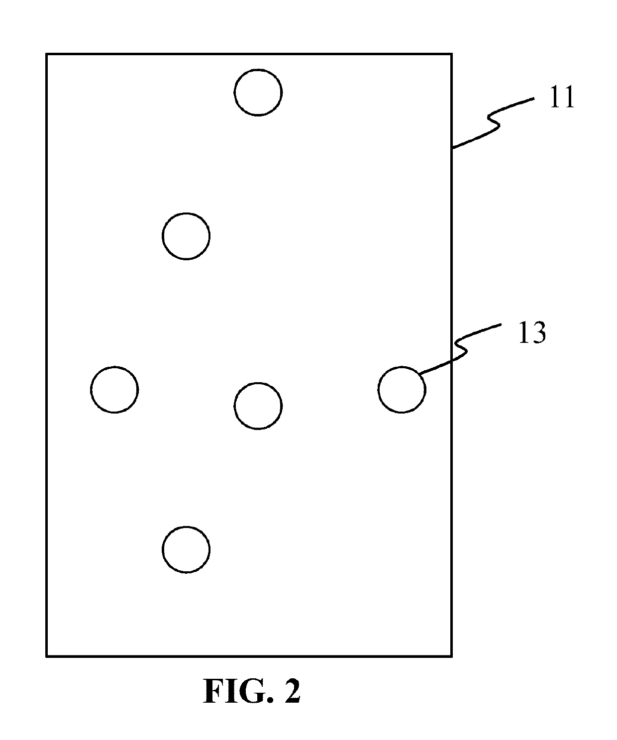
A structure, for defect inspection, is provided, which includes a scanning pad scanned by an electron beam inspection tool and a test key. The structure can be located in the scribe line. A virtual grounding pad is further provided if the test key is located in the dummy pattern regions.

Description

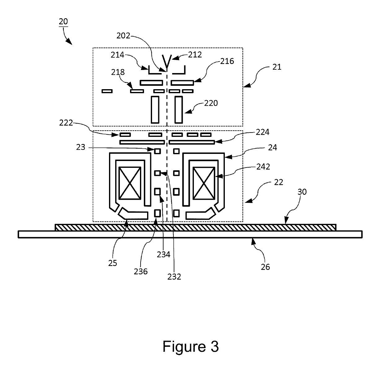
CLAIM OF PRIORITY[0001]This application claims the benefit of priority of U.S. provisional application No. 62 / 270,090 entitled to Yeh et al. filed Dec. 21, 2015 and entitled “Structure for Being Inspected by Using EBI”, the entire disclosures of which are incorporated herein by reference.BACKGROUND OF THE INVENTION[0002]1. Field of the Invention[0003]The present invention relates to a test device for defect inspection, and more particularly to a test device for VC mode defect inspection by using at least one charged particle beam.[0004]2. Description of the Prior Art[0005]Undoubtedly, compared to any other technology or knowledge, semiconductor devices not only impact nowadays society but also influence our daily life. Although it can be traced to two centuries ago, for example Alessandro Volta in 18th century and Michael Faraday in 19th century, the history of semiconductor development indeed influences mankind in commercial semiconductor devices is 20th century. In the first, vacu...

Claims


Application Information

Patent Timeline
Patent Type & Authority Patents(United States)
IPC IPC(8): G01R31/307H01J37/28
CPCH01J37/28G01R31/307H01J2237/221H01J2237/24564H01J2237/24592
Inventor YEH, CHANG-CHUN
Owner ASML NETHERLANDS BV
Learn More