Structure for a high resolution light-emitting device

a light-emitting device, high-resolution technology, applied in the direction of semiconductor devices, solid-state devices, organic semiconductor devices, etc., can solve the problem of substantially reducing the recombination of radiation

Active Publication Date: 2019-08-20
SHARP KK
View PDF4 Cites 4 Cited by
  • Summary
  • Abstract
  • Description
  • Claims
  • Application Information

AI Technical Summary

Benefits of technology

[0016]The embodiments of the present disclosure may provide high-resolution patterns of light-emitting devices having different respective configurations of emissive regions, which

Problems solved by technology

This band gap narrowing, combined with placing the narrowest band gap adjacent to the limiting charge transport layer, m

Method used


Image

  • Structure for a high resolution light-emitting device
  • Structure for a high resolution light-emitting device
  • Structure for a high resolution light-emitting device

Examples


example 2

n of a Bottom Emitting Light-Emitting Device

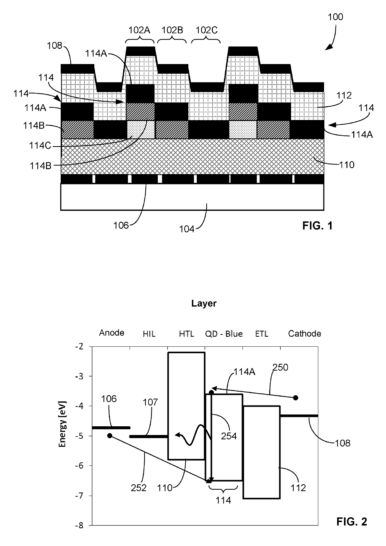
[0100]150 nm of ITO is sputtered through a shadow mask onto a 1 mm thick glass substrate to define a semi-transparent anode region. PEDOT:PSS in aqueous solution is deposited on top of the anode by spin coating then baked at 150° C. to form a hole injection layer. TFB dissolved in chlorobenzene is deposited on top of the hole injection layer by spin coating then baked at 110° C. to form a hole transport layer. CdSe / CdS quantum dots are deposited and patterned by a previously described deposition and patterning method. ZnO nanoparticles are deposited on top of the emissive layer by spin coating from ethanol followed by baking at 110° C. to form an electron transport layer. 100 nm of aluminum is thermally evaporated on top of the electron transport layer to provide a reflective cathode.

[0101]The above-described process produces a bottom emitting structure including: 1 mm glass substrate|150 nm ITO anode|50 nm PEDOT:PSS hole injection layer|3...


PUM


Abstract

A device includes a first light-emitting device and a second light-emitting device, each including an anode, a cathode, charge transport layers disposed between the anode and the cathode, and an emissive layer disposed between the charge transport layers. For the first light-emitting device, the emissive layer includes first quantum dots, the emissive layer configured to emit light at a first wavelength. For the second light-emitting device, the emissive layer includes emissive sub-layers provided in a stacked arrangement in a thickness direction. A first one of the emissive sub-layers includes the first quantum dots and is configured to emit light at the first wavelength, and a second one of the emissive sub-layers includes second quantum dots and is configured to emit light at a second wavelength different than the first wavelength.

Description

TECHNICAL FIELD[0001]The invention relates to light-emitting devices, and in particular light-emitting devices including solution processable emitting layers such as quantum dot LEDs. These light-emitting devices may be implemented in display applications, for example high resolution, multicolor displays. The invention further relates to methods of manufacturing said light-emitting devices.BACKGROUND ART[0002]A common architecture for a light-emitting device includes an anode and cathode; an emissive layer (EML) containing a material which emits light upon electron and hole recombination, such as an inorganic or organic semiconductor layer or layer of quantum dots (QDs); at least one hole transporting layer (HTL) between the anode and the emissive layer providing transport of holes from the anode and injection of holes into the emissive layer; and at least one electron transporting layer (ETL) between the cathode and the emissive layer providing transport of electrons from the catho...

Claims


Application Information

Patent Timeline
IPC IPC(8): H01L51/50H01L51/52H01L51/56H01L51/00H01L27/32
CPCH01L51/502H01L51/5278H01L51/5056H01L51/5072H01L51/5225H01L51/56H01L51/0017H01L51/5004H01L27/3211H01L2251/552H10K59/35H10K59/122H10K71/211H10K71/12H10K50/13H10K50/11H10K2101/40H10K50/115H10K50/16H10K50/15H10K2101/30H10K50/19H10K50/822H10K71/00H10K71/231
Inventor PALLES-DIMMOCK, JAMES ANDREW ROBERTBOARDMAN, EDWARD ANDREWSMEETON, TIM MICHAELANGIONI, ENRICO
Owner SHARP KK
Why Eureka
Try Eureka