Suction method, suction device, laser processing method, and laser processing device

a laser processing and suction device technology, applied in the direction of chemistry apparatus and processes, manufacturing tools, welding/soldering/cutting articles, etc., can solve the problems of insufficient suction force, limited suction force, and inability to obtain a high pressure reduction effect, so as to increase the suction speed of the suction product, prevent the efficiency of the processing from being lowered, and high recovery rate

Active Publication Date: 2019-10-29
FUKUI PREFECTURE
View PDF59 Cites 1 Cited by
  • Summary
  • Abstract
  • Description
  • Claims
  • Application Information

AI Technical Summary

Benefits of technology

[0027]In the present invention, it is possible to depressurize, with a simple method and device, a target position to the critical pressure or less and to perform suction, without moving the target into the chamber, even when the target is in the atmosphere by provision of the configuration described above. Furthermore, with the present invention, it is possible to suck and recover solid and liquid suction products and to obtain a high recovery rate. Moreover, since the pressure reduction effect is higher than a conventional suction device, it is possible to increase the suction speed of the suction product in comparison with the conventional suction device.
[0028]In laser processing, it is possible to remove or recover a by-product by pressurization of a laser irradiation portion, with the result that it is possible to obtain a high-quality processing surface without the re-adherence of the by-product. Moreover, the interruption of laser light by a by-product such as plasma or fume is suppressed by quick removal of a by-product from a laser irradiation region, with the result that it is possible to prevent the efficiency of the processing from being lowered.
[0029]Furthermore, even when, in laser processing, a processing target is in the atmosphere, a high-speed swirl flow is formed by jetting an inert gas such as compressed air, nitrogen or argon, and thus it is possible to reduce an oxygen partial pressure in the laser irradiation portion (by lowering an apparent oxygen concentration), with the result that it is possible to suppress the occurrence of combustion by laser irradiation.

Problems solved by technology

Furthermore, as another structural problem, when a gas is sucked from the suction port, a stagnation point where the flow speed is zero is generated on the surface of the suction target which is a suction point, and the pressure is increased to neat the atmospheric pressure at the stagnation point, with the result that the suction force becomes insufficient.
Therefore, in a method of sucking the target surface of a target by sucking a gas from a suction port, which is a general suction method, it is impossible to obtain a high pressure reduction effect, and thus a suction force is limited.
However, in the suction device, the suction force is limited due to the critical pressure and the stagnation point described above.
A vortex airflow is formed on the surface of a suction target, and thus it is possible to remove the stagnation point, which is one of the problems.
However, although, in Patent Literature 1, it is necessary to accelerate the rotation of the impeller wing to the sound speed in order that the pressure of the suction port may become equal to or less than the critical pressure, it is structurally difficult to realize the acceleration.
Even in the field of laser processing, in drilling and cutting processing, along with irradiation with laser light, the generation of molten metal particles such as sputters, metal vapors referred to as fumes and fine metal particles referred to as debris is a problem in the case of a metal material, whereas in the case of a resin material, the generation of soot, smoke and a combustion gas is a problem in the case of a resin material.
However, the devices according to the two inventions described above are designed assuming that a flat plate such as a liquid crystal panel or a flat panel display is a processing target, and when being applied to a shaped product having large surface irregularities, in the device of Patent Literature 3, it is difficult to remove a by-product because a flow is blocked by the surface irregularities, whereas in the device of Patent Literature 4, it is necessary to keep short a distance between the bottom portion of a laser processing machine and the irradiation surface of the processing target, when step differences in the processing surface are large, the effect of sucking the by-product is lowered, and thus it is not possible to prevent the by-product from adhering again to a processing cross section.
In order to more enhance the pressure reduction and suction effects produced by the swirl flow, it is necessary to increase the swirl speed of the swirl flow, but when the speed of the flow is increased, the thickness of the boundary layer in the vicinity of the wall surface is reduced and thus the effect of the viscosity is lowered and the flow site under the domination of inertia is formed, with the result that it becomes difficult to form the swirl flow.

Method used


Image

  • Suction method, suction device, laser processing method, and laser processing device
  • Suction method, suction device, laser processing method, and laser processing device
  • Suction method, suction device, laser processing method, and laser processing device

Examples


example 1

[0095]The results of an experiment on the pressure reduction effect of the suction device 100 as discussed above will be explained.

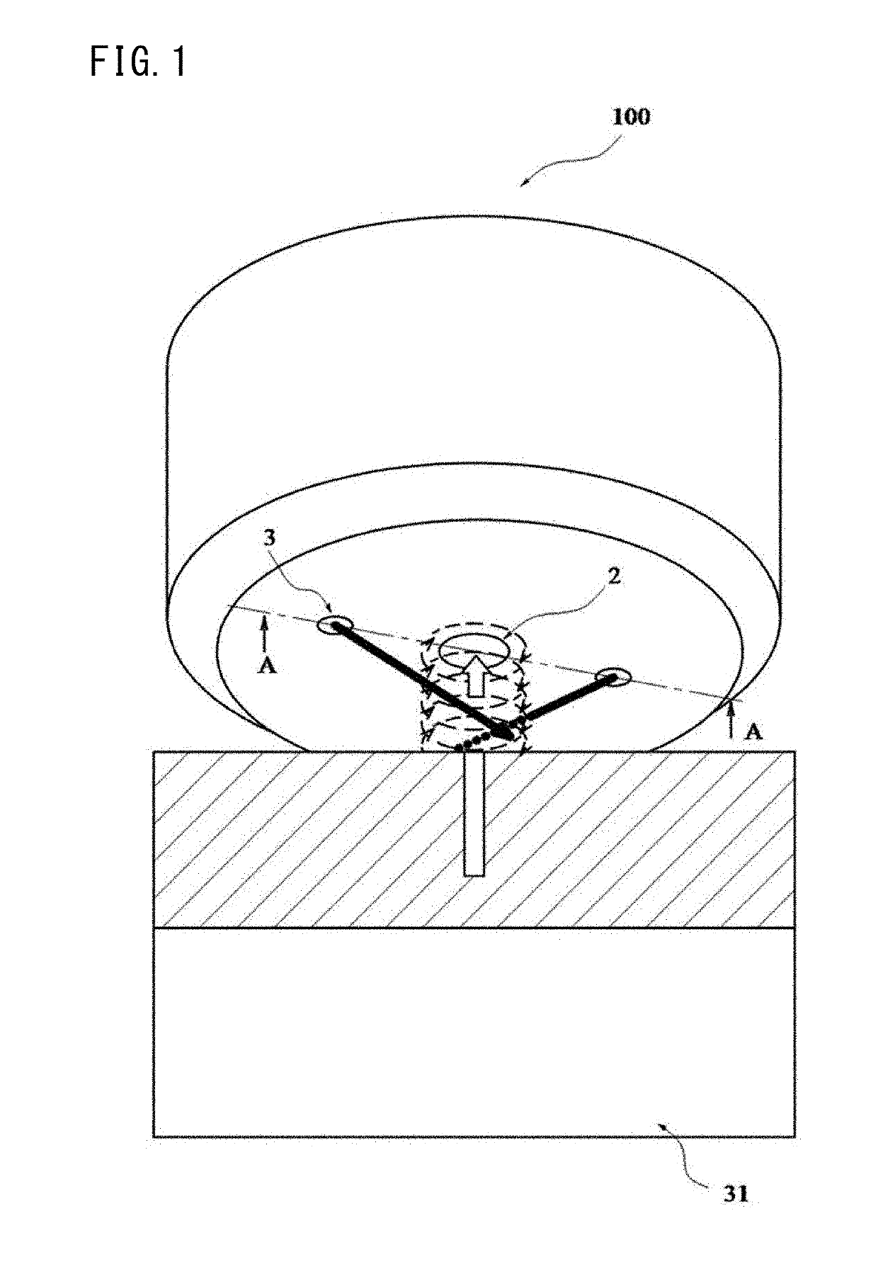
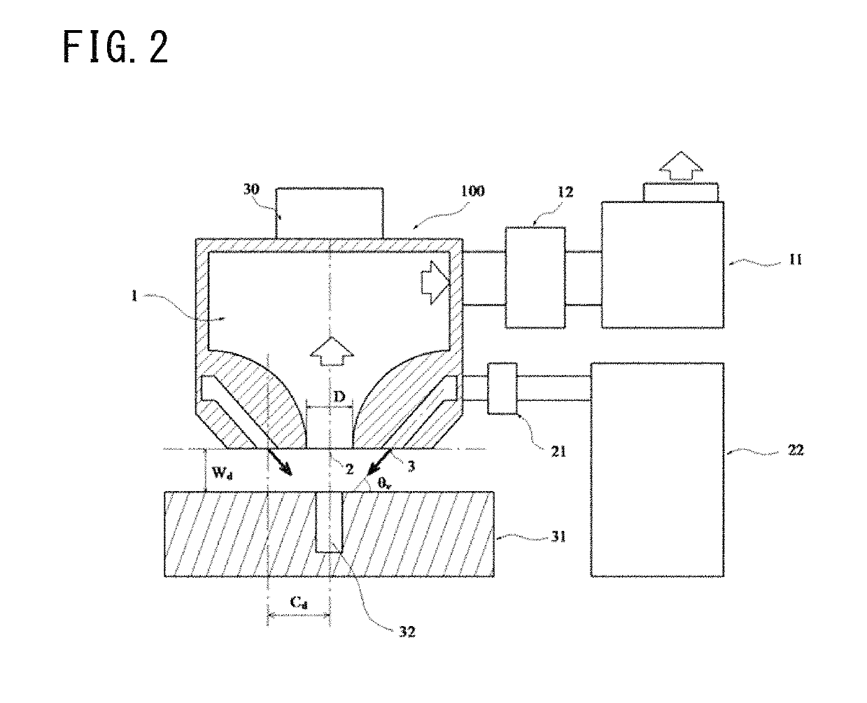
[0096]FIG. 2 is a vertical cross-sectional configuration diagram on the suction device 100 in the example. In the suction device 100 of the example, there were installed the suction port 2 sucking a gas into the pressure reduction chamber 1, the exhaust mechanism 11 exhausting the gas within the pressure reduction chamber 1, the jetting port 3 jetting the gas, the flow rate adjustment mechanism 21 adjusting the flow rate of the gas jetted, the gas introduction mechanism 22 introducing the gas into the jetting port 3 via the flow rate adjustment mechanism 21, and the operating distance adjustment means 30.

[0097]The suction device 100 had a structure in which the suction port 2 and the jetting port 3 were integrally formed, and was produced by a multilayer molding method. The shapes of the suction port 2 and the jetting port 3 were circular flat surfaces, ...

example 2

[0108]Next, the results of the observation of a flow site formed by the suction device 100 of Example 1 will be explained.

[0109]The configuration of the suction device 100 was the same as in Example 1, and model B in Table 1 was used. The target 31 was a transparent acrylic flat plate, and tracer particles for visualization were dispersed on the surface.

[0110]A camera was installed below the transparent acrylic flat plate such that the suction port 2 disposed in the bottom surface of the suction device 100 was able to be observed through the transparent acrylic flat plate. In order for a surface parallel to the bottom surface of the suction device 100 to be photographed, laser light of visible light was formed into the shape of a sheet parallel to the bottom surface of the suction device 100 and was caused to enter between the bottom surface of the suction device 100 and the transparent acrylic flat plate. In this way, scattered light when the tracer particles were absorbed by the s...

example 3

[0113]Then, the results of an experiment on the evaluation of the recovery rate of a suction product in the suction device 100 of Example 1 will be explained.

[0114]The configuration of the suction device 100 was the same as in Example 1, and model B in Table 1 was used.

[0115]The target to be sucked in the present example was water, and a concentration trap was used as the dust collection mechanism 12.

[0116]As in Example 1, the through-hole 32 having a diameter of 1 mm was formed in the surface of the target 31, and a hollow tube was made to communicate therewith. The tube was coupled to a container that stores the water serving as the target to be sucked. The water surface in the container was open to the atmosphere.

[0117]As a method of evaluating the recovery rate of the suction product, the water within the container was sucked and recovered using the suction device 100 as a method of evaluating the recovery rate of the suction product, and the recovery rate was calculated from a ...


PUM


Abstract

An object is to provide a suction method and a suction device which depressurize the pressure of the surface of a target installed in an open system to a critical pressure or less and which thereby can suck it and a laser processing device and a laser processing method using these. In a state where a predetermined operating distance is apart from a target installed in an open system and a suction port, the pressure of an inside of a pressure reduction chamber communicating with the suction port is set equal to or less than a critical pressure at which the speed of a gas sucked from the suction port is brought into a critical state; the jet speed of the gas in a jetting port from which the gas is jetted toward the target is set more than a Mach number of 0.2, the Mach number being obtained by dividing a jet speed of the gas by the sound speed of the gas jetted from the jetting port, the gas is jetted from the jetting port and is sucked by the suction port; a swirl flow is formed so as to surround the suction port between the surface of the target and the suction port; and thus the pressure of a central region of the swirl flow from the suction port to the surface of the target is reduced to the critical pressure or less and suction is performed.

Description

CROSS REFERENCE TO RELATED APPLICATIONS[0001]This application is a National Stage of International Application No. PCT / JP2015 / 058685 filed Mar. 23, 2015, claiming priority based on Japanese Patent Application No. 2014-066118 filed Mar. 27, 2014, the contents of all of which are incorporated herein by reference in their entirety.TECHNICAL FIELD[0002]The present invention relates to a suction method and a suction device which are opened to the atmospheric pressure, and also relates to a laser processing method and a laser processing device which use the suction method or the suction device to remove or recover a by-product generated at the time of laser processing.BACKGROUND ART[0003]It is known that when, in a system in which the suction port of a suction device is open to the atmosphere, a gas is isotropically sucked from the suction port by depressurization of the interior of the system of the suction device through the use of a pressure reduction device, in a case where the pressu...

Claims


Application Information

Patent Timeline
Patent Type & Authority Patents(United States)
IPC IPC(8): B23K26/00B23K26/40B08B5/04B08B15/04B23K26/14B23K26/38B08B5/02B23K26/16B23K26/142B23K103/04
CPCB08B5/04B08B5/02B23K26/16B23K26/38B08B15/04B23K26/40B23K26/142B23K26/1476B23K2103/05B08B2215/003
Inventor ASHIHARA, MASAAKI
Owner FUKUI PREFECTURE
Why Eureka
Try Eureka