Polycarbonate resin
a technology of polycarbonate resin and polycarbonate, applied in the field of polycarbonate resin, can solve problems such as residual strain, and achieve the effects of stable molded articles, low linear thermal expansion coefficient, and shrinkage after molding
- Summary
- Abstract
- Description
- Claims
- Application Information
AI Technical Summary
Benefits of technology
Problems solved by technology
Method used
Image
Examples
example 1
[0132]19.260 kg (43.921 mol) of 9,9-bis(4-(2-hydroxyethoxy)phenyl)fluorene (hereinafter, sometimes abbreviated as “BPEF”) having the following structure, 9.780 kg (45.655 mol) of diphenyl carbonate (hereinafter, sometimes abbreviated as “DPC”), and 2.21×10⁻² g (2.63×10⁻⁴ mol) of sodium hydrogen carbonate were placed into a 50-liter reactor equipped with a stirring machine and a distillation device, subjected to nitrogen replacement, and heated to 205° C. and stirred under a nitrogen atmosphere of 760 Torr for an hour.
[0133]
[0134]Following complete dissolution of the starting materials, the pressure reduction degree was adjusted to 150 Torr by spending 15 minutes, and maintained under the conditions of 205° C. and 150 Torr for 20 minutes to allow transesterification reaction. The temperature was further increased to 240° C. at a rate of 37.5° C. / hr, and maintained under the conditions of 240° C. and 150 Torr for 10 minutes. Thereafter, the pressure was adjusted to 120 Torr by spendin...
example 2
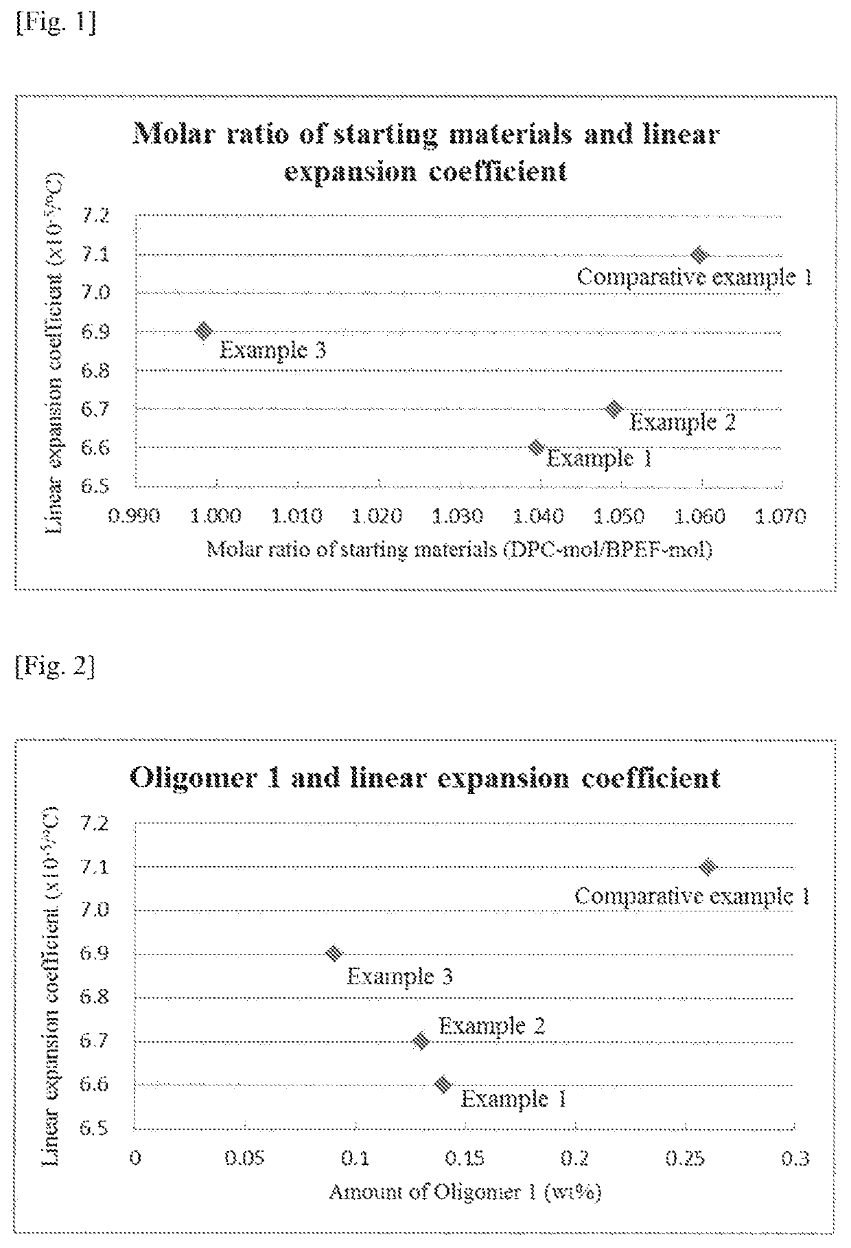
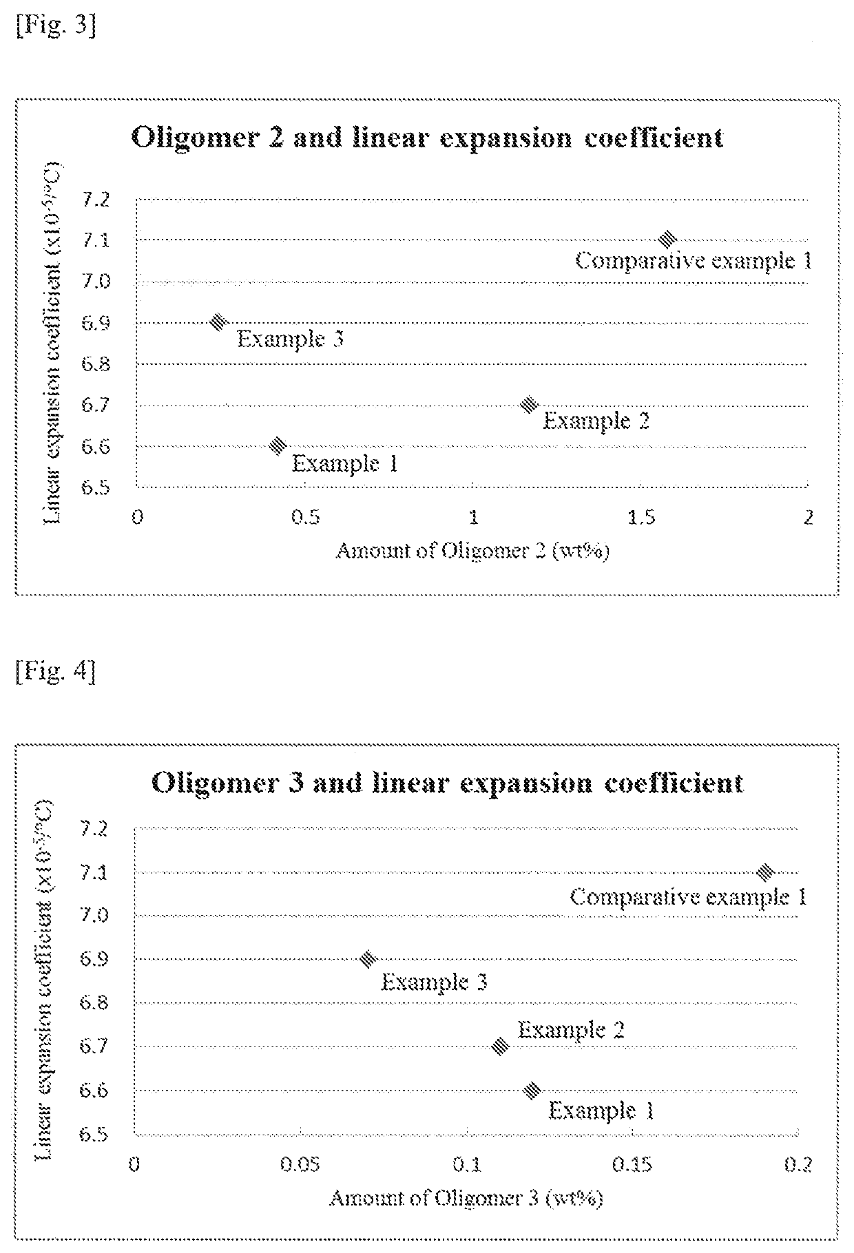
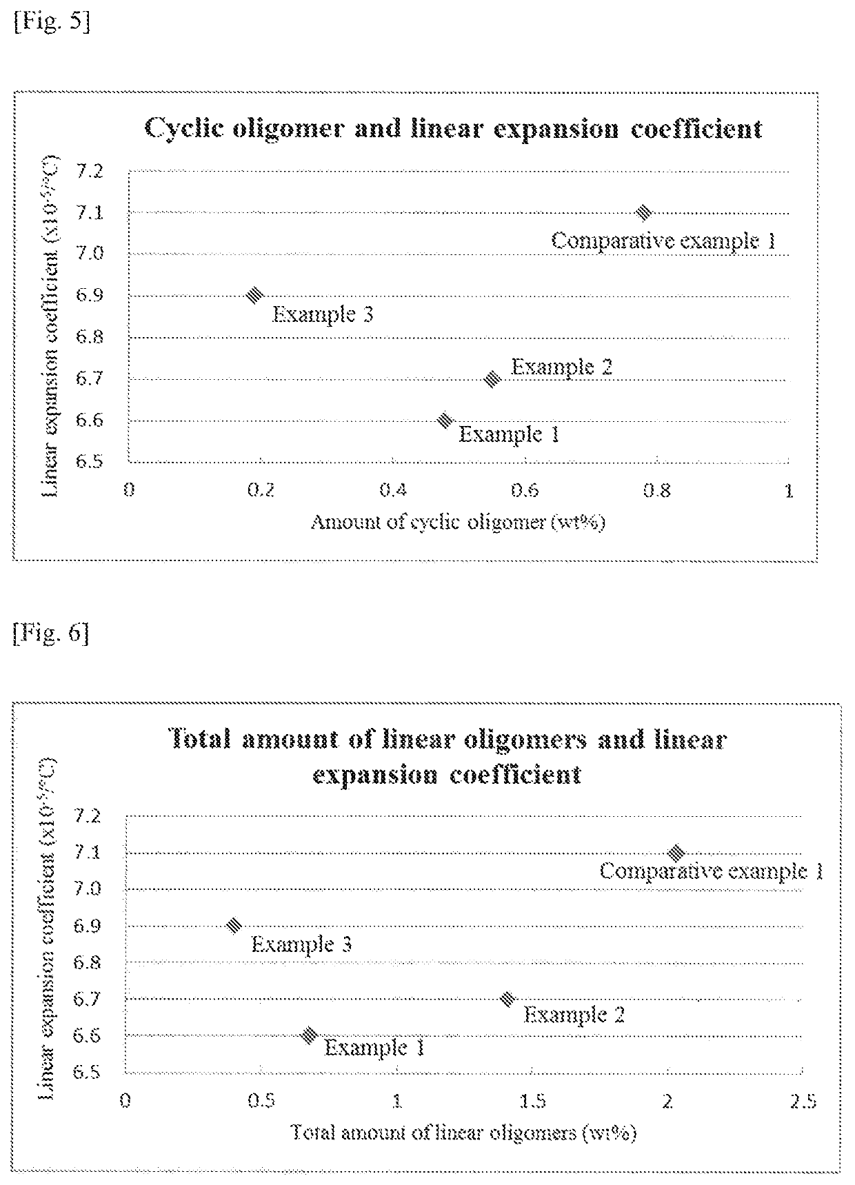
[0135]A polycarbonate resin was obtained in the same manner as Example 1 except that the amounts were changed as follows: 20.040 kg (45.700 mol) of BPEF, 10.271 kg (47.947 mol) of DPC and 2.30×10⁻² g (2.74×10⁻⁴ mol) of sodium hydrogen carbonate. Mw, amounts of the respective oligomers and linear expansion coefficient of the resulting resin are shown in Table 1. Specific amounts of the respective oligomers, namely, the contents with respect to the values of n, m, l and k in Formulae (1)-(4) are shown in Table 2. In addition, the relationship between the molar ratio of the starting materials used and the linear expansion coefficient is shown in FIG. 1 while the relationship between the amounts of the respective oligomers and the linear expansion coefficient are shown in FIGS. 2-6.
example 3
[0136]A polycarbonate resin was obtained in the same manner as Example 1 except that the amounts were changed as follows: 18.700 kg (42.644 mol) of BPEF, 9.120 kg (42.574 mol) of DPC and 2.21×10⁻² g (2.56×10⁻⁴ mol) of sodium hydrogen carbonate. Mw, amounts of the respective oligomers and linear expansion coefficient of the resulting resin are shown in Table 1. Specific amounts of the respective oligomers, namely, the contents with respect to the values of n, m, l and k in Formulae (1)-(4) are shown in Table 2. In addition, the relationship between the molar ratio of the starting materials used and the linear expansion coefficient is shown in FIG. 1 while the relationship between the amounts of the respective oligomers and the linear expansion coefficient are shown in FIGS. 2-6.
PUM
| Property | Measurement | Unit |
|---|---|---|
| Tg | aaaaa | aaaaa |
| Tg | aaaaa | aaaaa |
| Tg | aaaaa | aaaaa |
Abstract
Description
Claims
Application Information
 - R&D
- Intellectual Property
- Life Sciences
- Materials
- Tech Scout
- Unparalleled Data Quality
- Higher Quality Content
- 60% Fewer Hallucinations
Browse by: Latest US Patents, China's latest patents, Technical Efficacy Thesaurus, Application Domain, Technology Topic, Popular Technical Reports.
© 2025 PatSnap. All rights reserved.Legal|Privacy policy|Modern Slavery Act Transparency Statement|Sitemap|About US| Contact US: help@patsnap.com


