
Microangiography method and system based on full-space modulation spectrum splitting and angle compounding

a full-space modulation, angle compounding technology, applied in the field of oct (optical coherence tomography) and label-free three-dimensional optical coherence tomography angiography, can solve the problems of difficult detection, limited clinical application of conventional structural oct, and minor scattering difference between normal and diseased biological tissue, so as to prevent the degradation of transverse resolution

Active Publication Date: 2020-06-02
ZHEJIANG UNIV
View PDF2 Cites 0 Cited by
  • Summary
  • Abstract
  • Description
  • Claims
  • Application Information

AI Technical Summary

Benefits of technology

The present invention provides a method for obtaining an angiogram that has better contrast and connectivity of blood vessels. Additionally, the method prevents degradation in transverse resolution caused by the modulation spectrum splitting. Furthermore, the method allows for the measurement of absolute flow velocity of blood flow with a single beam and measurement.

Problems solved by technology

Usually, at an early stage of the disease, the light scattering difference between normal and diseased biological tissue is minor, which is difficult to be detected and distinguished by the conventional structural OCT.
So the conventional structural OCT has limited applications in clinical treatment.
The overlap between the dynamic and static signal statistic curve causes mistakes when distinguishing dynamic and static signals and suppress the blood flow contrast.
Compared to the original full wavelength spectrum, the bandwidth of each subspectrum is narrowed, which leads to degradation of axial resolution.

Method used


Image

  • Microangiography method and system based on full-space modulation spectrum splitting and angle compounding
  • Microangiography method and system based on full-space modulation spectrum splitting and angle compounding
  • Microangiography method and system based on full-space modulation spectrum splitting and angle compounding

Examples


Embodiment Construction

[0041]Referring to the drawings, according to a preferred embodiment of the present invention is illustrated, wherein

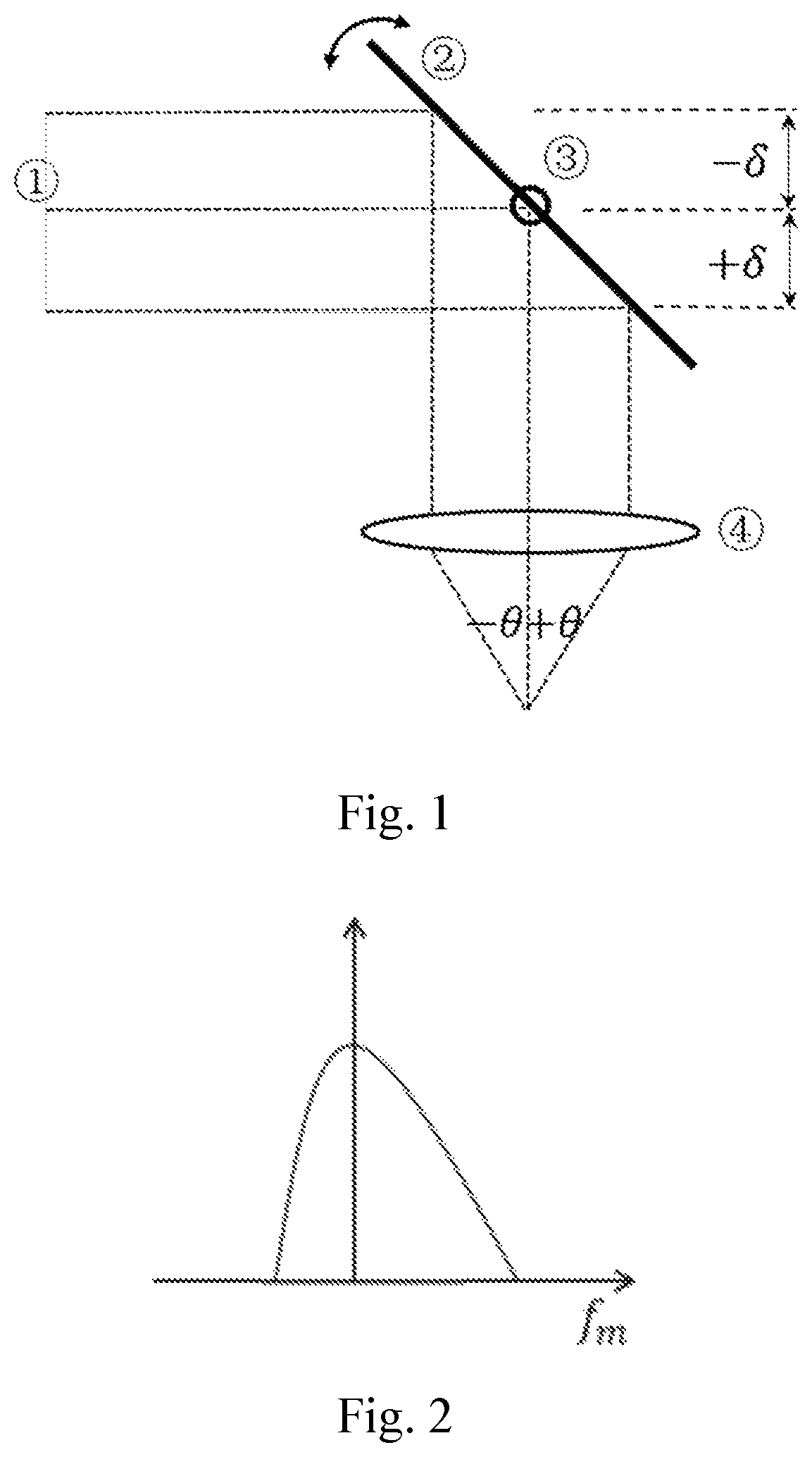
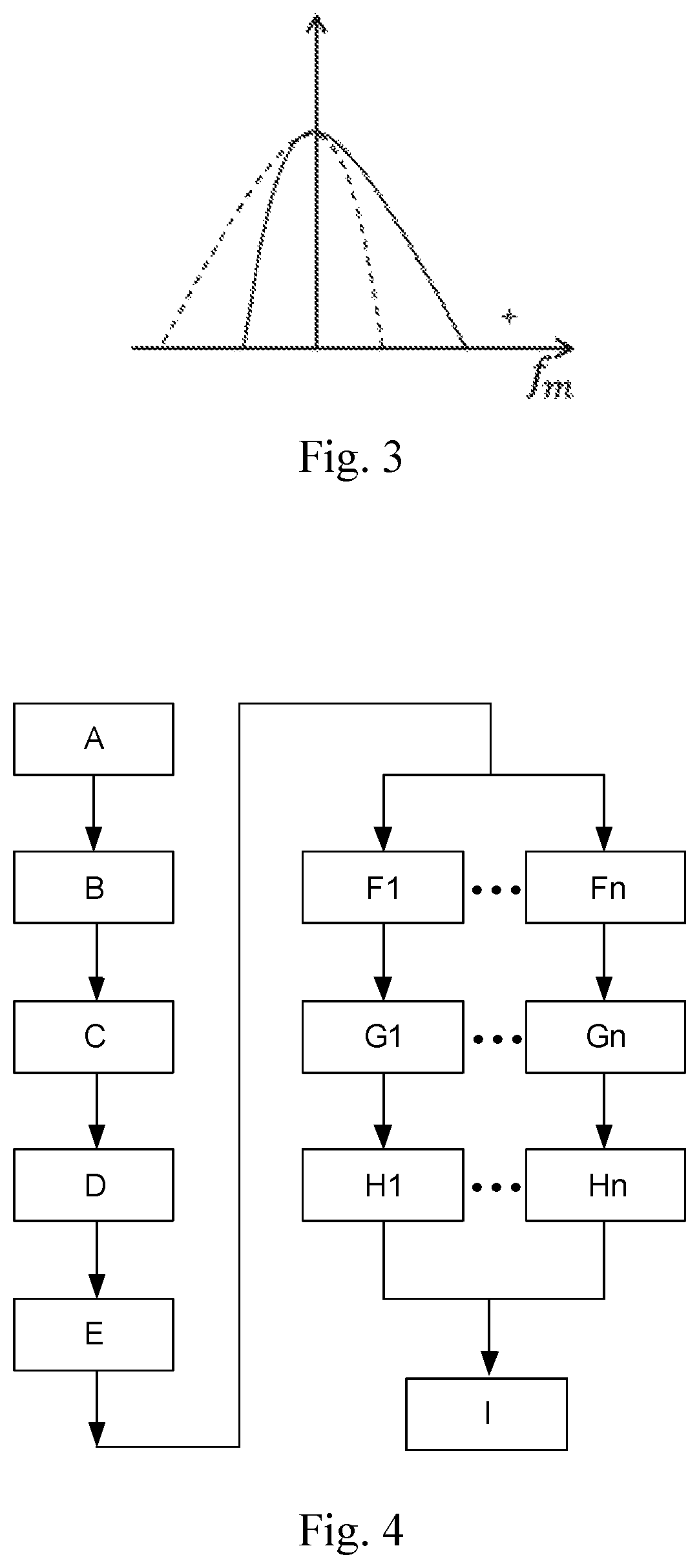
[0042]FIG. 1, FIG. 2 and FIG. 3 are illustrations of a transverse modulation theory of the present invention. Detailed explanations on FIG. 1, FIG. 2 and FIG. 3 are as below:

[0043]1) In the sample arm of the OCT system, usually the diameter of the light beam that hits on the objective is required to be as large as possible to obtain a high transverse imaging resolution. So, in FIG. 1, when a wide light beam is collimated on the center of the rotational axis of the sample arm scanning mirror, an offset δ occurs from the light beam to the center of the rotational axis. The offset δ induces the sample arm optical path modulation, which leads to the transverse scanning modulation in the spatial frequency domain (as shown in FIG. 2). The modulation frequency fm and offset δ is in a linear function:

[0044]fm=2⁢k⁢⁢δωπ,

[0045]Where k is the central wave number of the light sour...


PUM


Abstract

A microangiography method and system based on full-space modulation spectrum splitting and angle compounding is disclosed. Label-free three-dimensional optical coherence tomography angiography is realized by combining the three-dimensional space resolution capability of an optical coherence tomography and the motion recognition capability of a dynamic scattering technology. Probe light of different incident angles is encoded with a transverse scanning modulation spectrum in a spatial frequency domain, incident angle-resolved sub-angiograms which are independent of one another are obtained by splitting the modulation spectrum, and an angiogram with multiple space angles compounded is realized. Conjugate mirror images are removed from a depth (z) domain, a complex-valued OCT interference spectra are reconstructed, the full-space modulation spectrum is obtained in the spatial frequency domain, and the overlap of the modulation spectrum conjugate mirror images is avoided. And the absolute flow velocity of blood flow can be measured through a multi angle-resolved probing technology.

Description

CROSS REFERENCE OF RELATED APPLICATION[0001]This is a U.S. National Stage under 35 U.S.C 371 of the International Application PCT / CN2016 / 079693, filed Apr. 20, 2016, which claims priority under 35 U.S.C. 119(a-d) to CN 201610080511.8, filed Feb. 5, 2016.BACKGROUND OF THE PRESENT INVENTIONField of Invention[0002]The present invention relates to OCT (Optical Coherence Tomography) and label-free three-dimensional optical coherence tomography angiography (OCT Angiography; OCTA) based on OCT, and more particularly to a microangiography method and system based on full-space modulation spectrum splitting and angle compounding.Description of Related Arts[0003]OCT is a new imaging technique that has gradually developed since 1990s, which has significant applications in Biomedicine field. OCT draws attention from research workers from China and abroad to carry out further research by the advantages of label-free, non-invasive and non-contact characteristics, high resolution and high detective...

Claims


Application Information

Patent Timeline
Patent Type & Authority Patents(United States)
IPC IPC(8): G01B9/02A61B5/026A61B5/00A61B5/0275A61B3/10
CPCA61B5/02755A61B5/0079G01B9/02083A61B5/7275A61B5/0066G01B9/02044A61B5/7235A61B5/0261G01B9/02091A61B3/102G06T2207/10101A61B5/0073A61B5/0082
Inventor LI, PENGLI, PEICHENG, YUXUANZHOU, LIPINGDING, ZHIHUA
Owner ZHEJIANG UNIV
Learn More