Ammonia capture and recovery system and method for removing ammonia from a wastewater stream

a technology of ammonia capture and recovery system, applied in water/sewage treatment by neutralisation, water treatment parameter control, specific water treatment objectives, etc., to achieve the effect of reducing the dissolved solids, reducing the pressure on the water polisher section, and reducing the theoretical water recovery

Active Publication Date: 2020-06-09
NASA
View PDF8 Cites 3 Cited by
  • Summary
  • Abstract
  • Description
  • Claims
  • Application Information

AI Technical Summary

Benefits of technology

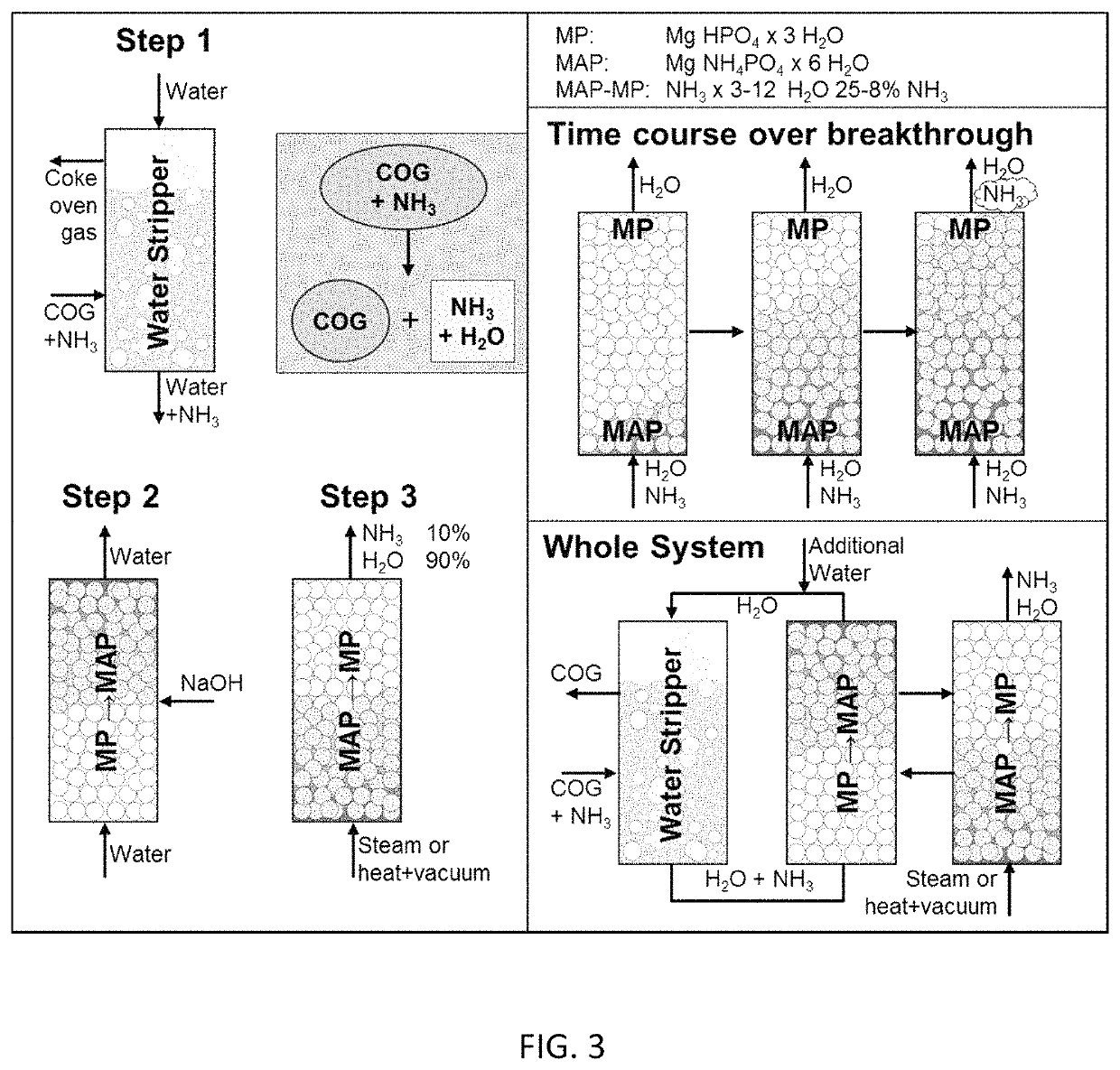
[0009]This ammonia capture and recovery system is optimized to remove ammonia at various concentrations from various wastewater sources with low contact time (i.e., residence time) and without adding any further substantial amounts of chemicals and / or microbes to the effluent (other than a basic solution to maintain the pH). This ammonia capture and recovery system uses a solid magnesium phosphate compound instead of multiple liquid influents, such as magnesium chloride, ammonia, and / or phosphoric acid, which simplifies control and reduces the complexity of the system. The solid magnesium phosphate compound allows plug-flow configurations to be used when effluent ammonia concentration is a priority over magnesium ammonium phosphate compound production. Using a solid magnesium phosphate compound also allows regeneration, and repeating the cycle does not require extra equipment.
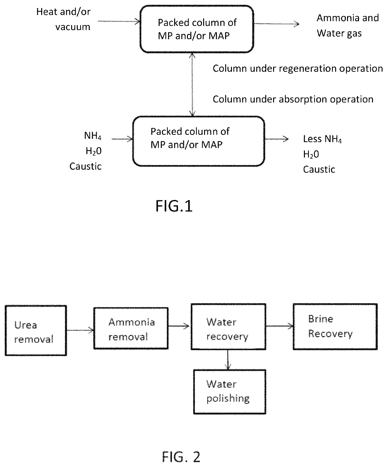
[0011]In order to handle short-term and long-term missions with or without hydroponic systems or brine recovery, an overall wastewater treatment system was devised including modular architecture to handle these requirements. Instead of stabilizing the urea, it made better sense to optimize and regulate its breakdown to ammonia which can then be selectively removed from the wastewater using the above-mentioned ammonia capture and recovery system. This allows the ammonia to be used for other purposes (e.g., nutrients, refrigeration, pressurizing gas as nitrogen, etc.) while simultaneously reducing the dissolved solids in the brine and allowing higher theoretical water recovery before salting out. Combining the wastewater streams allows efficient TOC and TN removal in all the streams and reduces the pressure on the water polisher section. Removing the ammonia (and urea) before water recovery prevents ammonia from reaching the polishing section and reducing the consumable demand. Without urea in the brine, brine recovery unit operations become more feasible and the de-brined brine can be recycled back to water recovery. This basic scheme is not confined to any specific unit operations, but allows various unit operations to be auditioned and rotated out to optimize the process. As long as the reaction goes to completion or near completion the wastewater treatment system functions as expected. Individual unit operations can be tried for each section and compared to each other to increase conversion, reduce size, lower consumable demand, or increase reliability. To fit with the modularity of the wastewater treatment system, the system goals and requirements can change and, with unit operations, changes can meet those requirements without scrapping the whole wastewater treatment system. Some of these changes can be as simple as running a different chemical reaction in a vessel or as complex as adding a plant growth system to augment food supplies. With this flexibility, this wastewater treatment system will not be immediately obsolete with ever changing mission requirements. By utilizing biological treatment systems that can perform different reactions in the same reactor the “agility” of the system can be increased.

Problems solved by technology

Advantages compared to biological systems mainly deal with complexity.

Method used


Image

  • Ammonia capture and recovery system and method for removing ammonia from a wastewater stream
  • Ammonia capture and recovery system and method for removing ammonia from a wastewater stream
  • Ammonia capture and recovery system and method for removing ammonia from a wastewater stream

Examples


example 1

orber

[0050]A 1 liter fluidized bed reactor is run in a batch mode. The influent contains 1 gram / liter ammonia-N at a starting pH of between 7 and 8. The reaction is started by fluidizing the bed according to the ergun equation. The bed material is made up of magnesium phosphate crystals of mean particle size of 300 microns with a Mg:PO4:NH3 ratio of 1.5:1.5:1. The bed is fluidized for between 1-3 hours until desired ammonia removal is reached. To quench the reaction the fluidization is ceased and the resulting mixture is drained from the reactor and filtered with a sieve. The crystals are collected for analysis or fertilizer use while the liquid is reduced in ammonia composition for further treatment. One hour of contact time with proper fluidization can reach 70% ammonia removal from the influent with the above parameters. pH is maintained at ˜8.5 using 1M NaOH or K2CO3 additions using bang-bang control with a deadtime of 5 minutes using 1 ml pulses of caustic.

example 2

orber (Single Pass)

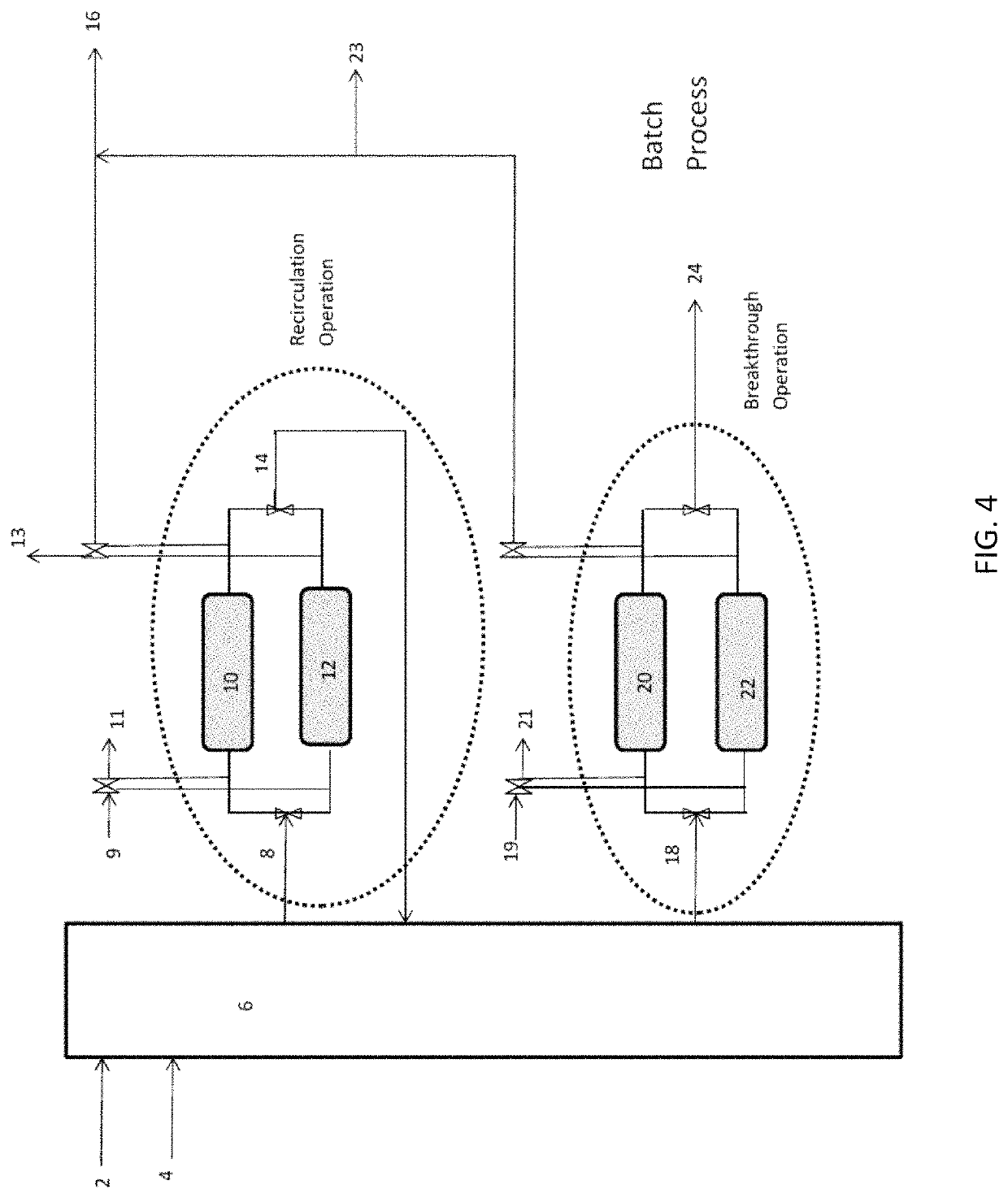
[0051]One liter plug flow reactor contains 1 kilogram of magnesium phosphate crystals at mean particle size of 100 microns packed on both sides with glass filters of mean pore size of 10 microns. Sufficient room is allowed for liquid contact and expansion of the particles when they sorb ammonia and water. 1 gram / liter ammonia-N containing wastewater is pumped into the reactor at between 0.1-100 bed volumes / hour and effluent is collected on the other side. Caustic is added to the influent and is controlled by pH setpoint of 8.5 at the effluent. When pH of the effluent dips below the setpoint, caustic is added to the influent in pulses, with the setpoint check at 5 minute intervals. The caustic of choice is NaOH at 1M concentration. When ammonia breakthrough is detected by an ammonia-sensitive ion selective probe or similar method, the plug flow reactor / column is swapped out for a fresh column. The column materials can be used as fertilizer or regenerated.

example 3

orber (Multipass)

[0052]A 1 liter plug flow reactor contains 1 kilogram of magnesium phosphate crystals at mean particle size of 100 microns packed on both sides with glass filters of mean pore size of 10 microns. Sufficient room is allowed for liquid contact and expansion of the particles when they adsorb ammonia and water. 1 gram / liter ammonia-N containing wastewater is pumped into the reactor at between 1-10 bed volumes / hour and recirculated back into the column. Caustic is added to the influent and is controlled by pH setpoint of 8.5 at the effluent. When pH of the effluent dips below the setpoint, caustic is added to the influent in pulses, with the setpoint check at 5 minute intervals. The effluent is routed back as an influent in a closed loop. When ammonia concentration in the plug flow reactor loop fails to decrease, the column is swapped out for a fresh column. The column materials can be used as fertilizer or regenerated.


PUM

PropertyMeasurementUnit
temperatureaaaaaaaaaa
mean particle sizeaaaaaaaaaa
pressureaaaaaaaaaa

Abstract

A wastewater stream including ammonia and water is fed to at least one packed column including packing material having a surface of solid magnesium phosphate or solid magnesium ammonium phosphate or both. Each of the packed columns is capable of cycling between an ammonia absorption operation and an ammonia regeneration operation. The magnesium phosphate compound reacts with the water and ammonia to form a magnesium ammonium phosphate compound. In one embodiment, this system provides for the regeneration of the magnesium ammonium phosphate compound for further use as an ammonia sorber. In another embodiment, the magnesium ammonium phosphate compound is used as fertilizer. Additionally, the ammonia capture and recovery system may be used in conjunction with other unit operations in an overall wastewater treatment system.

Description

CROSS-REFERENCE TO RELATED APPLICATIONS[0001]This application is a continuation-in-part of U.S. patent application Ser. No. 13 / 940,342 filed on Jul. 12, 2013, which claims the benefit of priority under 35 USC § 119(e) of U.S. Provisional Patent Application Ser. No. 61 / 671,306 filed on Jul. 13, 2012, the contents of which are incorporated herein by reference.ORIGIN OF THE INVENTION[0002]The invention described herein was made in the performance of work under NASA contracts and is subject to the provisions of Section 20135(b) of the National Aeronautics and Space Act, Public Law 111-314, § 3 (124 Stat. 3330, 51 U.S.C. Chapter 201 and 35 U.S.C. § 202), and may be manufactured and used by or for the Government for governmental purposes without the payment of any royalties thereon or therefore.BACKGROUND OF THE INVENTION1. Field of the Invention[0003]The present invention generally relates to an ammonia capture and recovery system that includes at least one packed column including packin...

Claims


Application Information

Patent Timeline
Patent Type & Authority Patents(United States)
IPC IPC(8): C02F1/28C02F101/16
CPCC02F1/281C02F2209/44C02F2303/16C02F2209/40C02F2209/03C02F2101/16C02F2209/06C02F1/66C02F2101/38C02F2201/001
Inventor LUNN, GRIFFIN M.GLEICH, ANDREW F.MONJE, OSCAR A.WORRELL, JULIA M.
Owner NASA
Why Eureka
Try Eureka