Evaporation management in digital microfluidic devices

a microfluidic device and digital microfluidic technology, applied in the field of digital microfluidic devices, can solve the problems of increasing the cost and complexity of the microfluidic device, limiting the utility of air-matrix dmf, and evaporation frequently limiting the utility of the air-matrix dmf, so as to achieve the effect of reducing evaporation

Active Publication Date: 2020-06-30
MIROCULUS
View PDF306 Cites 5 Cited by
  • Summary
  • Abstract
  • Description
  • Claims
  • Application Information

AI Technical Summary

Benefits of technology

[0009]The present invention relates to air-matrix digital microfluidic (DMF) apparatuses and related methods that minimize evaporation even at increase evaporative conditions (e.g., elevated temperature, reduced humidity, etc.) by coordinating the application of additional fluid (e.g., rehydrating) to droplets, e.g., reaction droplets, being manipulated by an air-matrix DMF apparatus. For example, in an air-matrix DMF apparatus, reaction droplets may be replenished with medium, e.g., reaction reagents, at controlled temperature and volume to ensure that the reaction mixture retains the proper concentration and activity through the reaction process.
[0010]A typical DMF apparatus may include parallel plates separated by an air gap; one of the plates (typically the bottom plate) may contain a patterned array of individually controllable electrodes, and the opposite plate (e.g., the top plate) may include a continuous grounding electrode. Alternatively, grounding electrode(s) can be provided on the same plate as the actuating / high-voltage electrodes. The surfaces of the plates in the air gap may include a dielectric insulator with a hydrophobic material to decrease the wettability of the surface and to add capacitance between the droplet and the control electrode. The droplets may be manipulated in the air gap space between the plates, and may include or have access to a starting material or materials and any reaction reagents. The air gap may be divided up into regions, as some regions of the plates may include heating / cooling (e.g., by Peltier device, resistive heating, convective heating / cooling, etc. in thermal contact with the region) localized to that region. Detection (including imaging or other sensor-based detection) may also be provided over one or more localized regions; in some variations imaging may be provided over all or the majority of the reaction region (air gap space).
[0013]The method and apparatuses described herein may generally increase the reaction hydration in droplets on a DMF device, thus obviating the need for a humidified chamber or for a material (e.g., oil) or special chamber to prevent or limit evaporation. Instead, evaporation of the reaction fluid (e.g., solvent, water, media, etc.) is permitted, and instead addition of treated (e.g., heated) reaction fluid is automatically added to droplets when an appropriate trigger threshold is reached. The methods and apparatuses described herein may allow execution of biochemical reactions using air-matrix DMF over a range of temperatures (for example, but not limited to, 4-95° C.) and incubation times (for example, but not limited to, at least one hour). In one embodiment, the invention provides timely replenishment of p reaction volume using pre-heated droplets of solvent. Through this approach, the reaction volume and temperature may be maintained relatively constant (≤20% and ≤1° C. change, respectively) over the course of the biochemical reaction. This may therefore enable the use of an air-matrix DMF device in executing multiple biochemical reactions, and in particular, the use of air-matrix DMF for performing amplification and detection of polynucleotides (e.g., RNA fragmentation, first-strand cDNA synthesis, and PCR), including those drawn from a gene expression analysis workflow. Surprisingly, the inventors have found that the resulting reaction products are essentially indistinguishable from those generated by conventional bench-scale methods.
[0027]The volume of the replenishing droplet may configured to prevent over-dilution of the reaction droplet, which may interfere with whatever reaction is being carried out by the reaction droplet. For example, the volume of the replenishing droplet may be between about 10% and about 55% the volume of the reaction droplet (e.g., between about 10% and about 50%, between about 15% and about 40%, between about 20% and about 40%, etc.).
[0036]Thermal regulation of the thermal zone(s) of the air-matrix DMF apparatus may be enhanced by using one or more thermal void regions between and / or at least partially around the thermal zones of the air-matrix DMF. A thermal void region may include a cut-out or open region (gap). For example, any of these apparatuses may include at least one thermal void adjacent to the thermal zone and configured to prevent or reduce the transfer of thermal energy between the thermal zone and unit cells outside of the thermal zone. For example, an air-matrix DMF may include a tubing adapter configured to couple to the aperture to form the replenishing droplet.

Problems solved by technology
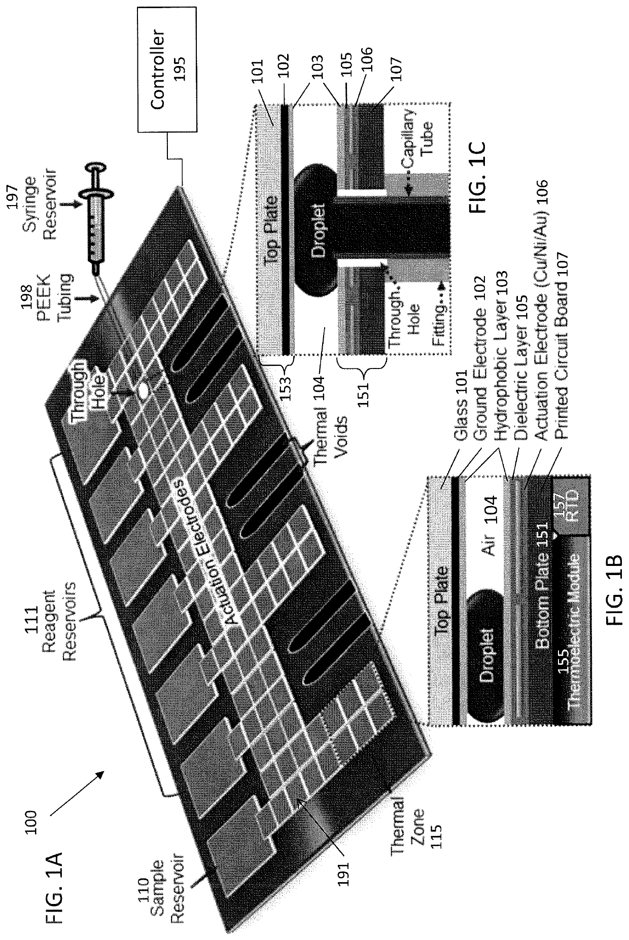
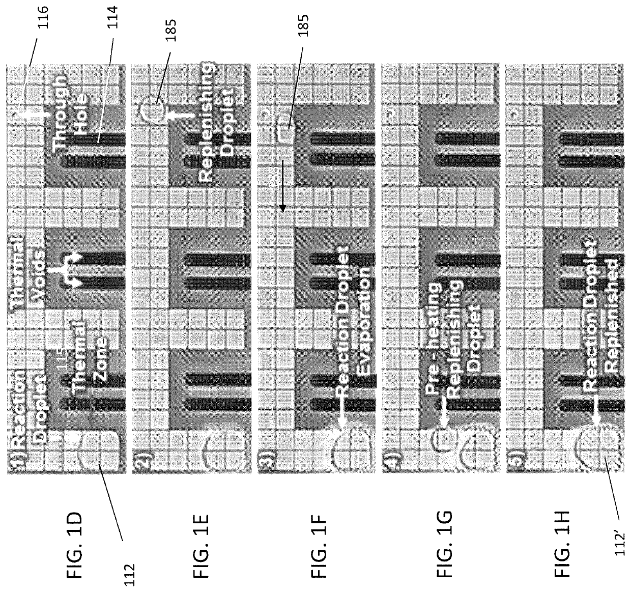
While traditional biochip type devices utilize micro- or nano-sized channels and corresponding micropumps, microvalves, and microchannels coupled to the biochip to manipulate the reaction steps, these additional components increase cost and complexity of the microfluidic device.
However, use of the air-matrix format necessitates accounting for droplet evaporation, especially when the droplets are subjected to high temperatures for long periods of time.
In biochemical contexts, however, evaporation frequently limits the utility of air-matrix DMF, because enzymatic reactions are often highly sensitive to changes in reactant concentration.
Largely for this reason, investigators have attempted to use oil-matrix DMF for biochemical applications, despite numerous drawbacks including: 1) the added complexity of incorporating gaskets or fabricated structures to contain the oil; 2) unwanted liquid-liquid extraction of reactants into the surrounding oil; 3) incompatibility with oil-miscible liquids (e.g., organic solvents such as alcohols); and 4) efficient dissipation of heat, which undermines localized heating and often confounds temperature-sensitive reactions.
Another strategy is to place the air-matrix DMF device in a closed humidified chamber, but this often results in unwanted condensation on the DMF surface, difficult and / or limited access to the device, and need for additional laboratory space and infrastructure.
These issues may be avoided by transferring reaction droplets from the air-matrix DMF device to microcapillaries, where they can be heated in dedicated off-chip modules without evaporation problems, however, this complicates design and manufacture of the air-matrix DMF device, introducing the added microcapillary interfaces and coordination with peripheral modules.

Method used


Image

  • Evaporation management in digital microfluidic devices
  • Evaporation management in digital microfluidic devices
  • Evaporation management in digital microfluidic devices

Examples


example 1

RNA Extraction

[0088]For extraction of total RNA from human PBMC, 5-10×106 cells were centrifuged at 1,000 rpm at 4° C. for 5 min, and re-suspended in 1 ml of RNAzol (Molecular Research Center; Cincinnati, Ohio), followed by dilution with 400 μl of water. After incubation at room temperature (RT) for 15 min, the samples were centrifuged at 16,000 rpm at 4° C. for 15 min, and ˜800 μl of the aqueous phase from each tube were transferred to a new 2-ml tube and mixed 1:1 with ethanol. Purified total RNA was recovered using the Direct-zol kit (Zymo Research; Irvine, Calif.), following the manufacturer's instructions and eluting in 10 μL of water. RNA yield was quantified using a Qubit 2.0 fluorimeter (Life Technologies; Carlsbad, Calif.), and fragment size distribution was assessed using a 2100 Bioanalyzer equipped with an RNA Nano 6000 Chip (Agilent; Santa Clara, Calif.). RNA samples were stored at −80° C.

example 2

RNA Fragmentation

[0089]DMF-mediated RNA fragmentation was implemented in three steps. First, three droplets (0.5 μL each) containing 180 ng / μL of human PBMC total RNA (270 ng RNA final) and a droplet (0.5 μL) of diluted 10×NEBNext fragmentation buffer (New England Biolabs; Ipswitch, Mass.) (4× final) were dispensed from their respective reservoirs, mixed on the DMF surface for 10 sec, and transported to a thermal zone. Second, the reaction droplet (2 μL; 270 ng RNA and 1× fragmentation buffer final) was incubated at 94° C. for 3 min. Finally, the reaction was cooled to 4° C., and RNA fragmentation was terminated by supplementing the reaction with a droplet (0.5 μL) of NEBNext stop solution (New England Biolabs; Ipswitch, Mass.). The reaction volume was maintained through addition of six replenishing droplets of nuclease-free distilled water (0.5 μL each) over the course of the experiment. For RNA fragmentation using the conventional benchscale method, processing was identical except...

example 3

cDNA Synthesis

[0090]First-strand cDNA synthesis was accomplished through DMF or benchscale implementation of the Peregrine method. For DMF-mediated cDNA synthesis, a five-step protocol was developed. First, a 0.5 μL droplet of fragmented human PBMC total RNA (100 ng) and a 0.5 μL droplet of primer PP_RT (25 mM) were dispensed from their respective reservoirs, merged and mixed on the DMF surface, and the 1 μL droplet transported to a thermal zone. Second, the droplet was incubated at 65° C. for 2 min, and then immediately cooled to 4° C. Third, three droplets of master mix [0.5 μL_each, containing 45% of SMARTScribe 5× First-Strand Buffer (Clontech; Mountain View, Calif.), 5.5% of 20 mM DTT, 22% of 10 mM dNTP mix, 5.5% of RiboGuard RNase inhibitor (Epicentre; Madison, Wis.) and 22% of SMARTScribe Reverse Transcriptase (Clontech; Mountain View, Calif.), as well as Pluronic F127 at 0.1% w / v) were dispensed onto the DMF surface, merged with the 1 μL droplet, and the reaction incubated a...


PUM

PropertyMeasurementUnit
temperaturesaaaaaaaaaa
temperatureaaaaaaaaaa
timeaaaaaaaaaa

Abstract

Described herein are digital microfluidic (DMF) devices and corresponding methods for managing reagent solution evaporation during a reaction. Reactions on the DMF devices described here are performed in an air or gas matrix. The DMF devices include a means for performing reactions at different temperatures. To address the issue of evaporation of the reaction droplet especially when the reaction is performed at higher temperatures, a means for introducing a replenishing droplet has been incorporated into the DMF device. A replenishing droplet is introduced every time when it has been determined that the reaction droplet has fallen below a threshold volume. Detection and monitoring of the reaction droplet may be through visual, optical, fluorescence, colorimetric, and / or electrical means.

Description

CROSS REFERENCE TO RELATED APPLICATIONS[0001]This application claims priority to U.S. provisional patent application 62 / 171,772, “DEVICES AND METHODS FOR REACTION HYDRATION”, filed on Jun. 5, 2015 and herein incorporated by reference in its entirety.INCORPORATION BY REFERENCE[0002]All publications and patent applications mentioned in this specification are herein incorporated by reference in their entirety to the same extent as if each individual publication or patent application was specifically and individually indicated to be incorporated by reference.FIELD[0003]This application generally relates to digital microfluidic (DMF) apparatuses and methods. In particular, the apparatuses and methods described herein are directed to replenishing droplets when using DMF in air.BACKGROUND[0004]In recent years, efforts have been directed toward both automating and miniaturizing chemical and biochemical reactions. The lab-on-a-chip and biochip devices have drawn much interest in both scienti...

Claims


Application Information

Patent Timeline
Patent Type & Authority Patents(United States)
IPC IPC(8): G01N27/447B01L3/00B01L7/00
CPCB01L3/502792B01L3/502715B01L7/525B01L3/502784B01L2300/1822B01L2300/1805B01L2300/0867B01L2400/0427B01L2200/16B01L2200/142B01L2200/143
Inventor JEBRAIL, MAISRENZI, RONALD FRANCISBRANDA, STEVEN
Owner MIROCULUS
Why Eureka
Try Eureka