
Formulations and methods for 3D printing of ceramic matrix composites

a ceramic matrix and composite technology, applied in the field of monomer formulations, can solve the problems of low fracture toughness, limited thermal shock resistance, brittle failure, etc., and achieve the effect of inhibiting the degradation of solid-phase fillers

Active Publication Date: 2020-08-11
HRL LAB
View PDF22 Cites 3 Cited by
  • Summary
  • Abstract
  • Description
  • Claims
  • Application Information

AI Technical Summary

Benefits of technology

The patent describes a method for making ceramic structures with improved properties. The method involves using specific chemicals called functional additives that are added to a preceramic polymer to increase its volume and reduce shrinkage during the process of heat treatment. These functional additives are chemically bonded to the monomers using surface treatments, such as silane compounds. The use of sacrificial materials that selectively degrade during high-temperature pyrolysis can also help prevent degradation of the solid-phase fillers during this process. Overall, this method can produce ceramic structures with better strength and quality.

Problems solved by technology

Ceramic matrix composite (CMC) materials overcome many disadvantages of conventional ceramics, such as brittle failure, low fracture toughness, and limited thermal shock resistance.
No mature method for 3D printing ceramic matrix composites exists.
Currently, CMC materials are limited to manual lay-up, molding, or thermoforming.
Ceramic structures are typically sintered as compacted porous materials, severely limiting the manufacturable geometries.
These are typically unreinforced ceramics that do not contain a second phase and suffer from low fracture toughness.
In comparison with metals and polymers, ceramics are difficult to process, particularly into complex shapes.
Because they cannot be cast or machined easily, ceramics are typically consolidated from powders by sintering or deposited in thin films.
This processing challenge has limited the ability to take advantage of ceramics' impressive properties, including high-temperature capability, environmental resistance, and high strength.
All these techniques are limited by slow fabrication rates, and in many cases, a time-consuming binder removal process.
By starting with powders that need to be consolidated to a dense part, it is an almost insurmountable challenge to add reinforcement and create ceramic matrix composites without fusing or reacting the matrix and the second phase, losing reinforcing capability.
Furthermore, many additive processes introduce large thermal gradients that tend to cause cracks in ceramics.
Pores, cracks, and inhomogeneities are often responsible for the low strength and poor reliability of additively manufactured ceramic parts.

Method used


Image

  • Formulations and methods for 3D printing of ceramic matrix composites
  • Formulations and methods for 3D printing of ceramic matrix composites
  • Formulations and methods for 3D printing of ceramic matrix composites

Examples


example 1

on of 3D-Printing Composition for SiC / SiOC UV-Cured Ceramic Matrix Composite

[0277]A monomer mixture containing 100 parts of vinylmethoxysiloxane polymer, 100 parts of (mercaptopropyl)methylsiloxane polymer, 0.5 parts of 2,2-dimethyl-2-phenylacetophenone, 0.15 parts of tert-butylhydroquinone, and 0.25 parts of 2,2′-(2,5-thiophenediyl)bis(5-tert-butylbenzoxazole) (all parts by weight), is thoroughly blended to make sure the components are well-mixed and the mixture is a uniform system. This resin is capable of forming a silicon oxycarbide (SiOC) ceramic phase when polymerized and thermally treated.

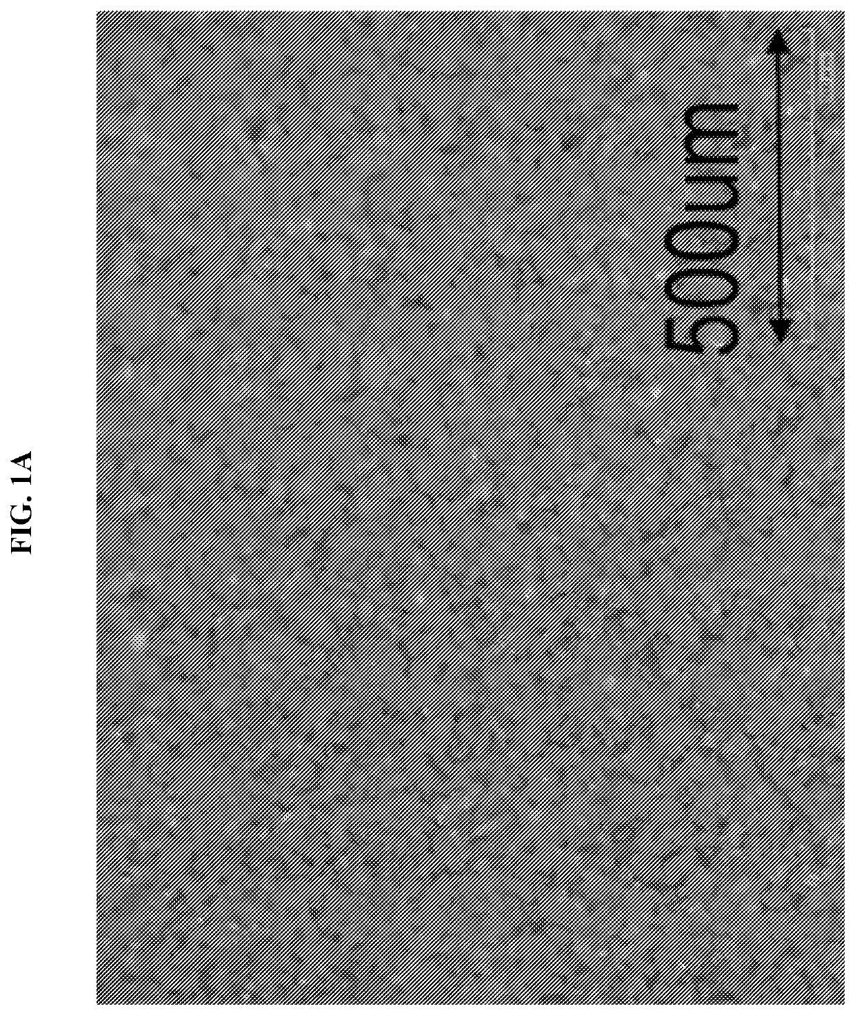
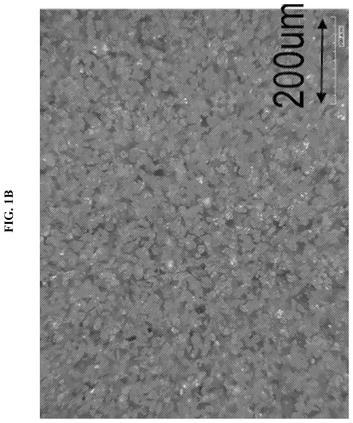
[0278]Then 25% by weight silicon carbide (SiC) powder with 50 μm particle size is blended and sonicated to disperse the SiC particles into the above resin. The SiC microparticles serve as solid-phase fillers in the SiOC-forming resin. The mixture is then ready for use as a monomer formulation in UV-cured 3D printing.

[0279]Optical microscope images of SiC solid-phase fillers dispersed in the ...

example 2

n of 3D-Printed, UV-Cured SiC / SiOC Ceramic Matrix Composite

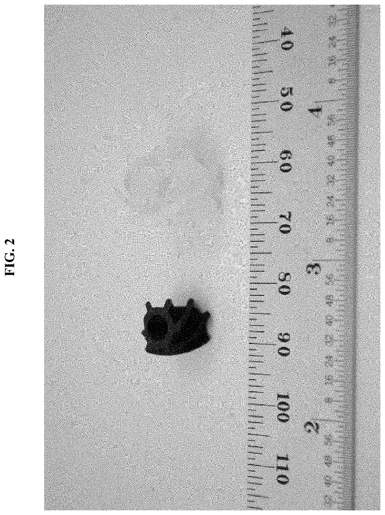
[0280]The monomer formulation of Example 1 is 3D-printed and UV-cured, followed by thermal treatment to form a ceramic matrix composite. Bulk parts are demonstrated by curing layers at 385 nm with LED-UV to form a preceramic polymer, and then pyrolyzing the preceramic polymer at 1000° C. in inert atmosphere to form a pyrolyzed ceramic material. FIG. 2 shows a photograph of the preceramic polymer (right-hand side) and the darker pyrolyzed ceramic part (left-hand side).

[0281]FIG. 3 is a graph of thermogravimetric analysis for the pyrolysis of the UV-cured preceramic polymer into a pyrolyzed ceramic material, measuring the loss of sample mass over time as the pyrolysis temperature increases.

[0282]The versatility and the applications of these preceramic resin formulations make them especially useful. A variety of applications in the automotive and aerospace industries, among others, may benefit from the ability to 3D-print high-...


PUM

PropertyMeasurementUnit
diameteraaaaaaaaaa
diameteraaaaaaaaaa
vol %aaaaaaaaaa

Abstract

This invention provides resin formulations which may be used for 3D printing and pyrolyzing to produce a ceramic matrix composite. The resin formulations contain a solid-phase filler, to provide high thermal stability and mechanical strength (e.g., fracture toughness) in the final ceramic material. The invention provides direct, free-form 3D printing of a preceramic polymer loaded with a solid-phase filler, followed by converting the preceramic polymer to a 3D-printed ceramic matrix composite with potentially complex 3D shapes or in the form of large parts. Other variations provide active solid-phase functional additives as solid-phase fillers, to perform or enhance at least one chemical, physical, mechanical, or electrical function within the ceramic structure as it is being formed as well as in the final structure. Solid-phase functional additives actively improve the final ceramic structure through one or more changes actively induced by the additives during pyrolysis or other thermal treatment.

Description

PRIORITY DATA[0001]This patent application is a non-provisional application with priority to U.S. Provisional Patent App. No. 62 / 428,203, filed Nov. 30, 2016; U.S. Provisional Patent App. No. 62 / 428,207, filed Nov. 30, 2016; and U.S. Provisional Patent App. No. 62 / 428,213, filed Nov. 30, 2016, and U.S. Provisional Patent App. No. 62 / 556,388, filed Sep. 9, 2017, each of which is hereby incorporated by reference herein.FIELD OF THE INVENTION[0002]The present invention generally relates to monomer formulations suitable for making preceramic polymers, which can be converted into ceramic matrix composites and other ceramic structures.BACKGROUND OF THE INVENTION[0003]Ceramic matrix composite (CMC) materials overcome many disadvantages of conventional ceramics, such as brittle failure, low fracture toughness, and limited thermal shock resistance. Applications of ceramic matrix composites include those requiring reliability at high temperatures (beyond the capability of metals or polymers) ...

Claims


Application Information

Patent Timeline
Patent Type & Authority Patents(United States)
IPC IPC(8): C04B35/56C09D11/03B28B1/00C09D7/61B29C64/10C04B35/80C04B35/64C04B35/634C04B35/628C04B35/622B33Y70/00C04B35/597C08L83/08C04B35/571C04B35/589C04B35/58C09D11/037C09D11/101C09D11/102B33Y40/00B33Y80/00B29C64/379C09D7/40C09D7/62C09D5/33C08G77/18C08K3/34B29C64/129B29C35/08B29C71/02C08G77/28C08G77/20C08K9/04C08K7/10C08K7/00B33Y10/00B29K83/00B29K105/00B29K509/04
CPCB29C64/10C04B35/64B33Y80/00C09D7/62C04B35/62836C04B35/62839B33Y40/00C09D11/037C09D11/101C09D7/69C04B35/597C09D11/102B28B1/001C09D11/03C04B35/5603C04B35/515C04B35/62218C04B35/589B29C64/379C09D7/68B33Y70/00C09D5/004C04B35/63448C09D7/70C04B35/58C09D7/61C04B35/571C09D7/67C08L83/08C08L83/00C08K2201/005C08K9/04C04B2235/3895B33Y10/00B29K2995/003C04B2235/96C08K3/34B29C2035/0827B29C71/02C04B2235/483C08G77/18B29K2995/0026C04B2235/5216B29C64/129C04B2235/6026B29C2035/0838C04B2235/3826C04B2235/6562B29K2083/00C04B2235/6565C04B2235/5436C08K7/10C08G77/20C08K7/00C08G77/28C04B2235/77B29K2105/0002B29K2509/04C04B35/58028C04B35/58014C04B35/563C04B35/44C04B35/5622C04B35/5611C04B35/532C04B35/46C04B35/488C04B35/117C04B35/14C04B35/565C04B35/62842C04B35/581C04B35/62802C04B35/62844C04B35/62865C04B35/62868C04B35/62873C04B35/62876C04B2235/526C04B2235/5264C04B2235/5224C04B2235/5232C04B2235/5236C04B2235/524C04B2235/5276C04B2235/5284C04B2235/5292C04B2235/5454C04B35/80B33Y40/10B33Y40/20B33Y70/10Y02P10/25
Inventor SCHAEDLER, TOBIAS A.ECKEL, ZAK C.BIESBOER, SCOTTCANTE, KENNETH
Owner HRL LAB
Learn More