
Semiconductor device and method of manufacturing semiconductor device

a semiconductor device and semiconductor technology, applied in the direction of process and machine control, radiation controlled devices, instruments, etc., can solve the problems of reducing the coverability of an insulating layer between a through electrode and a semiconductor substrate, and reducing so as to reduce the degradation of characteristics or the reliability of a semiconductor device, and the effect of reducing productivity

Active Publication Date: 2020-08-25
CANON KK
View PDF23 Cites 0 Cited by
  • Summary
  • Abstract
  • Description
  • Claims
  • Application Information

AI Technical Summary

Benefits of technology

The invention aims to provide a semiconductor device and a way to make it that can prevent issues like decreased performance or reduced reliability without hurting productivity.

Problems solved by technology

When a scallop shape is formed on the side surface of the via-hole, this reduces the coverability of an insulating layer for insulation between a through electrode and a semiconductor substrate or a barrier metal portion that prevents a metal material forming the through electrode from diffusing into the semiconductor substrate.
Reduction in coverability of an insulating layer or a barrier metal portion may cause degradation in characteristics or reduction in reliability of a semiconductor device.
However, since the technique disclosed in Japanese Patent Application Laid-Open No. 2012-190826 requires a separate step of filling a resin in a via-hole and a step of removing an unnecessary resin, the number of steps is increased, which in turn may cause increase of a manufacturing cost.
Further, a larger aspect ratio of a via-hole makes it difficult to fill a resin to the bottom portion of the via-hole, and the unevenness of the side surface of the via-hole cannot be sufficiently smoothed.
Further, although a method other than the Bosch method is also known as a method of forming a via-hole, the productivity of the known method is low, because the etching rate is low compared to the Bosch method and formation of a via-hole requires long time.

Method used


Image

  • Semiconductor device and method of manufacturing semiconductor device
  • Semiconductor device and method of manufacturing semiconductor device
  • Semiconductor device and method of manufacturing semiconductor device

Examples


first embodiment

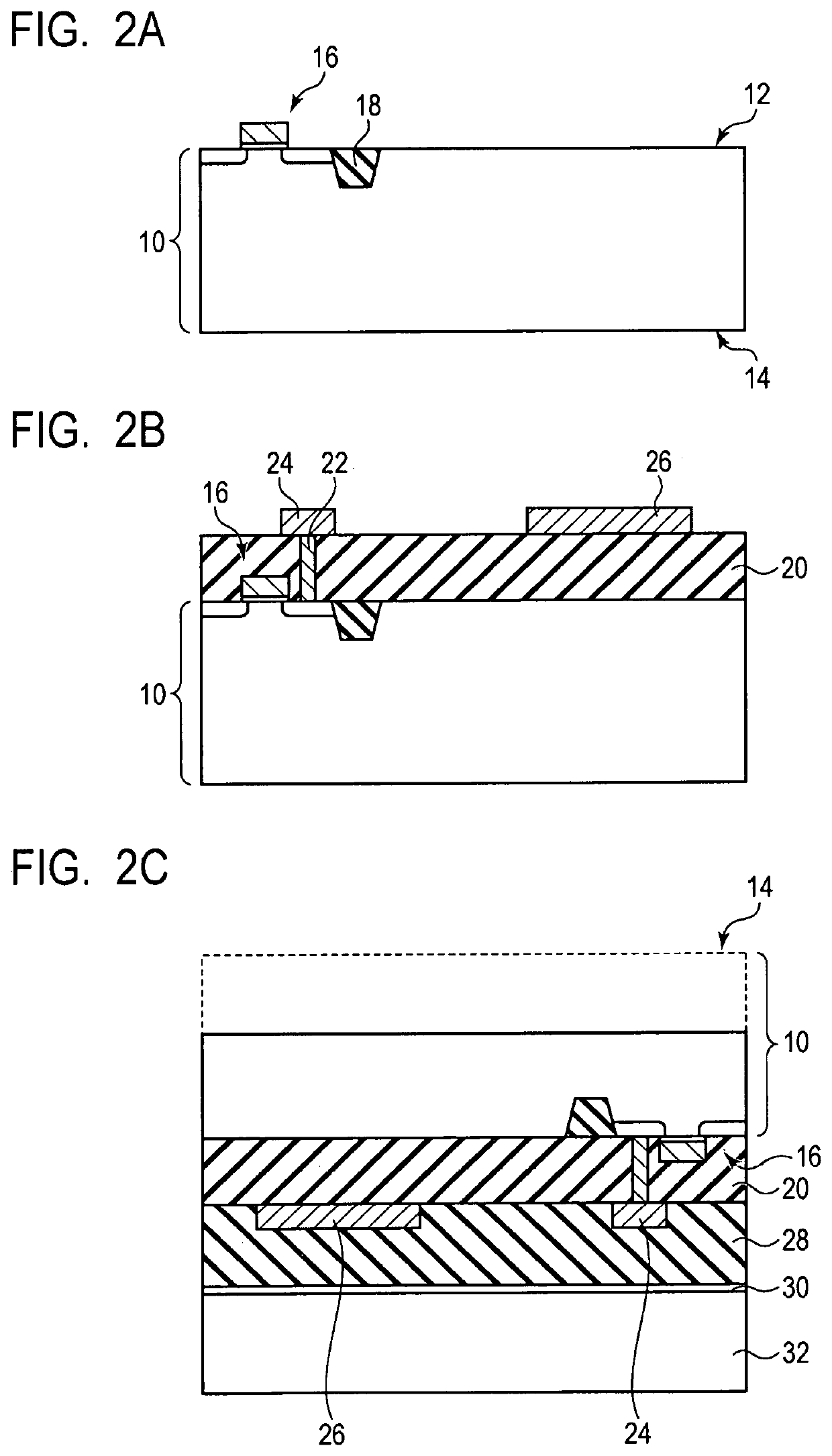
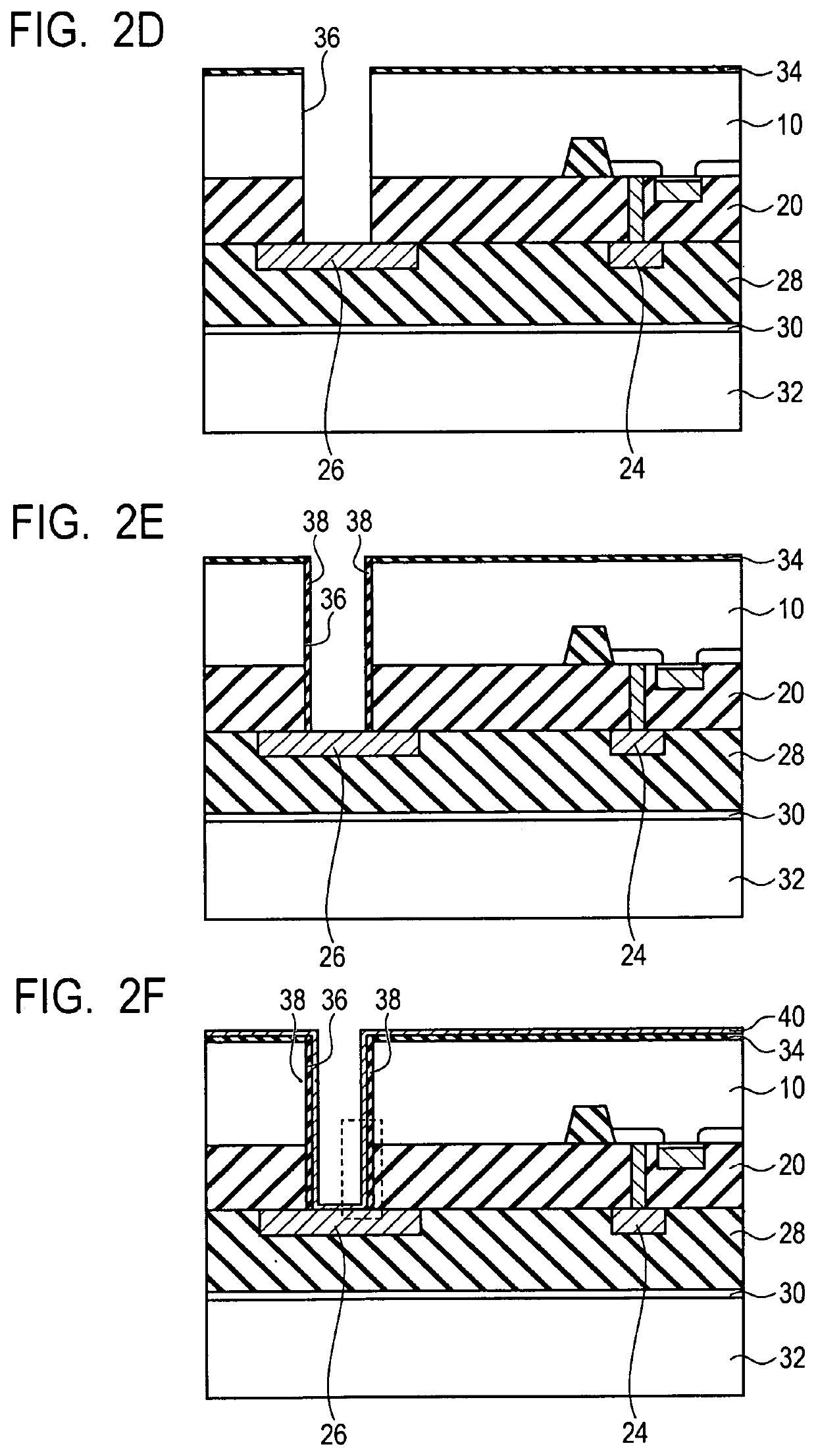
[0017]A semiconductor device and a method of manufacturing the same according to a first embodiment of the present invention will be described with reference to FIG. 1A to FIG. 3B.

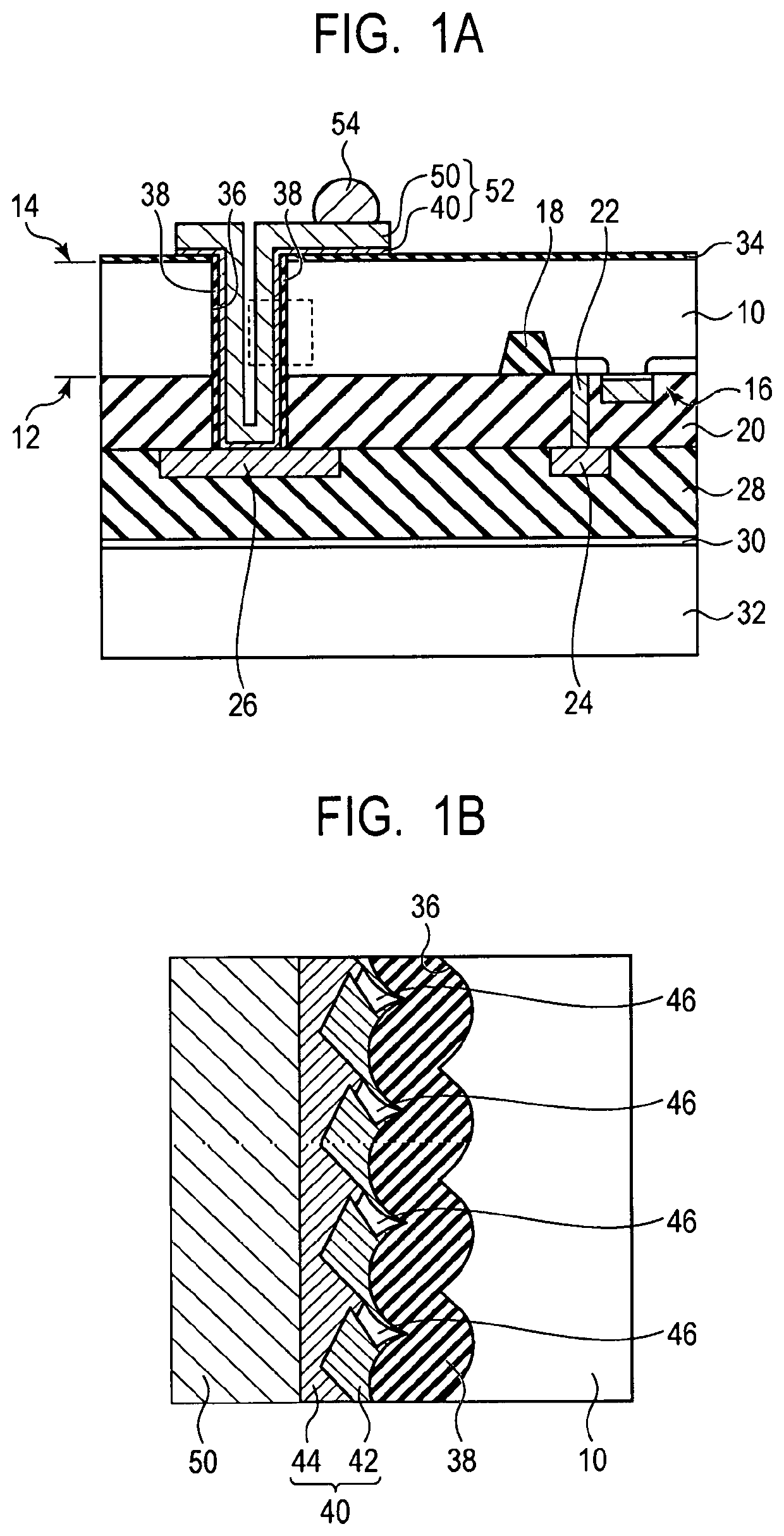
[0018]First, the structure of the semiconductor device according to the present embodiment will be described by using FIG. 1A and FIG. 1B. FIG. 1A is a schematic cross-sectional view illustrating the structure of the semiconductor device according to the present embodiment. FIG. 1B is an enlarged view of the area surrounded by a dotted line in FIG. 1A.

[0019]As illustrated in FIG. 1A, the semiconductor device according to the present embodiment includes a semiconductor substrate 10. A semiconductor element 16 is provided on the side of a first surface 12 that is one surface of the semiconductor substrate 10. An interlayer insulating film 20 is provided over the first surface 12 of the semiconductor substrate 10 on which the semiconductor element 16 is provided. A contact plug 22 electrically connected to th...

second embodiment

[0068]A semiconductor device and a method of manufacturing the same according to a second embodiment of the present invention will be described with reference to FIG. 4. Similar components to those of the first embodiment and the manufacturing method thereof illustrated in FIG. 1A to FIG. 3B are labeled with the same reference numerals, and the description thereof will be omitted or simplified. FIG. 4 is a schematic cross-sectional view illustrating a semiconductor device and a method of manufacturing the same according to the present embodiment.

[0069]A semiconductor device according to the present embodiment is the same as the semiconductor device according to the first embodiment illustrated in FIG. 1A except for a configuration of the barrier metal portion 40 being different. FIG. 4 is an enlarged view inside a frame surrounded by a dotted line in FIG. 1A.

[0070]The barrier metal portion 40 of the semiconductor device according to the present embodiment includes the first layer 42...

modified embodiment

[0089]The present invention is not limited to the above embodiments, and various modifications are available.

[0090]For example, the configuration of the semiconductor device described in the above embodiments is not particularly limited and are applicable to various semiconductor devices such as a logic device, a memory device, an imaging device, and the like. Further, the semiconductor device described in the above embodiments is applicable to various electronic equipment. The electronic equipment is not particularly limited, for example, a digital still camera, a video camera, a smartphone, a personal computer, a household appliance (IoT), and the like can be illustrated as examples.

[0091]Further, the semiconductor device described in the above embodiments is also applicable to a transportation equipment having a moving apparatus. The semiconductor device of the present embodiment overcomes problems caused by metal diffusion or stress and can ensure high reliability even when moun...


PUM

PropertyMeasurementUnit
thicknessaaaaaaaaaa
thicknessaaaaaaaaaa
thicknessaaaaaaaaaa

Abstract

A semiconductor device disclosed includes a semiconductor substrate, an electrode layer arranged over the semiconductor substrate, and a conductive member provided in an opening and electrically connected to the electrode layer, and the opening penetrates the semiconductor substrate and reaches the electrode layer. The conductive member includes a metal portion and a barrier metal portion provided between a side surface of the opening and the metal portion, the barrier metal portion includes a first layer and a second layer provided between the first layer and the metal portion, and the second layer is denser than the first layer.

Description

BACKGROUND OF THE INVENTIONField of the Invention[0001]The present invention relates to a semiconductor device and a method of manufacturing the semiconductor device.Description of the Related Art[0002]A semiconductor device (a semiconductor chip) of a solid-state imaging device or the like includes, for example, a semiconductor substrate on which an element such as a transistor or the like is formed, an insulating layer arranged over the semiconductor substrate, and an interconnection portion arranged inside the insulating layer. The interconnection portion includes an interconnection pattern that connects one element to another, an interconnection pattern that supplies power to an element, and the like. Further, the semiconductor device further includes an electrode portion for an electrical connection to an external device (such as another semiconductor device or circuit substrate). A part of the interconnection portion is connected to the electrode portion.[0003]When a semicondu...

Claims


Application Information

Patent Timeline
Patent Type & Authority Patents(United States)
IPC IPC(8): H01L27/146G05D1/02H01L31/0224
CPCH01L27/14683H01L27/14636H01L31/022408G05D1/0246H01L27/14643H01L21/76898H01L21/76868H01L21/76843
Inventor OSHIGE, HIDEMASA
Owner CANON KK
Learn More