
Film forming method, storage medium, and film forming system

a film forming and storage medium technology, applied in the direction of coatings, photomechanical coating apparatus, solid-state devices, etc., can solve the problem of not improving the uniformity of the film thickness, and achieve the effect of increasing the uniformity of the in-plane pattern formed in the recessed portion of the wafer and decreasing productivity

Active Publication Date: 2021-10-12
TOKYO ELECTRON LTD
View PDF18 Cites 0 Cited by
  • Summary
  • Abstract
  • Description
  • Claims
  • Application Information

AI Technical Summary

Benefits of technology

The patent describes a technique that allows for the formation of a highly uniform coating on a substrate that has both projections and recesses on its surface. This technique does not decrease productivity and can increase the in-plane uniformity of a pattern formed in a recessed portion of the substrate.

Problems solved by technology

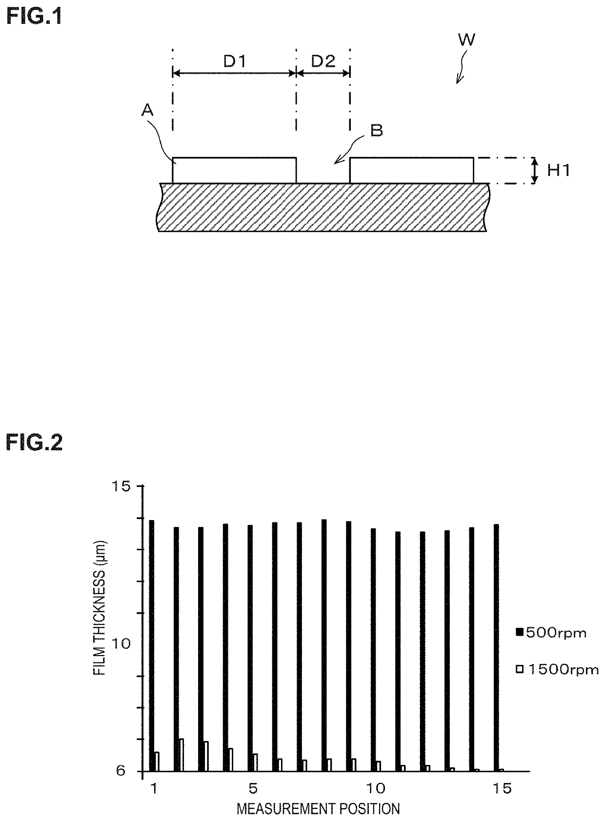
However, if the resist film R having a film thickness of several micrometers is formed by spin coating on the surface with the projections and recesses having the pitch and depth on the above-described high orders, not only projections and recesses appear on the surface of the resist film R but the following problem arises.
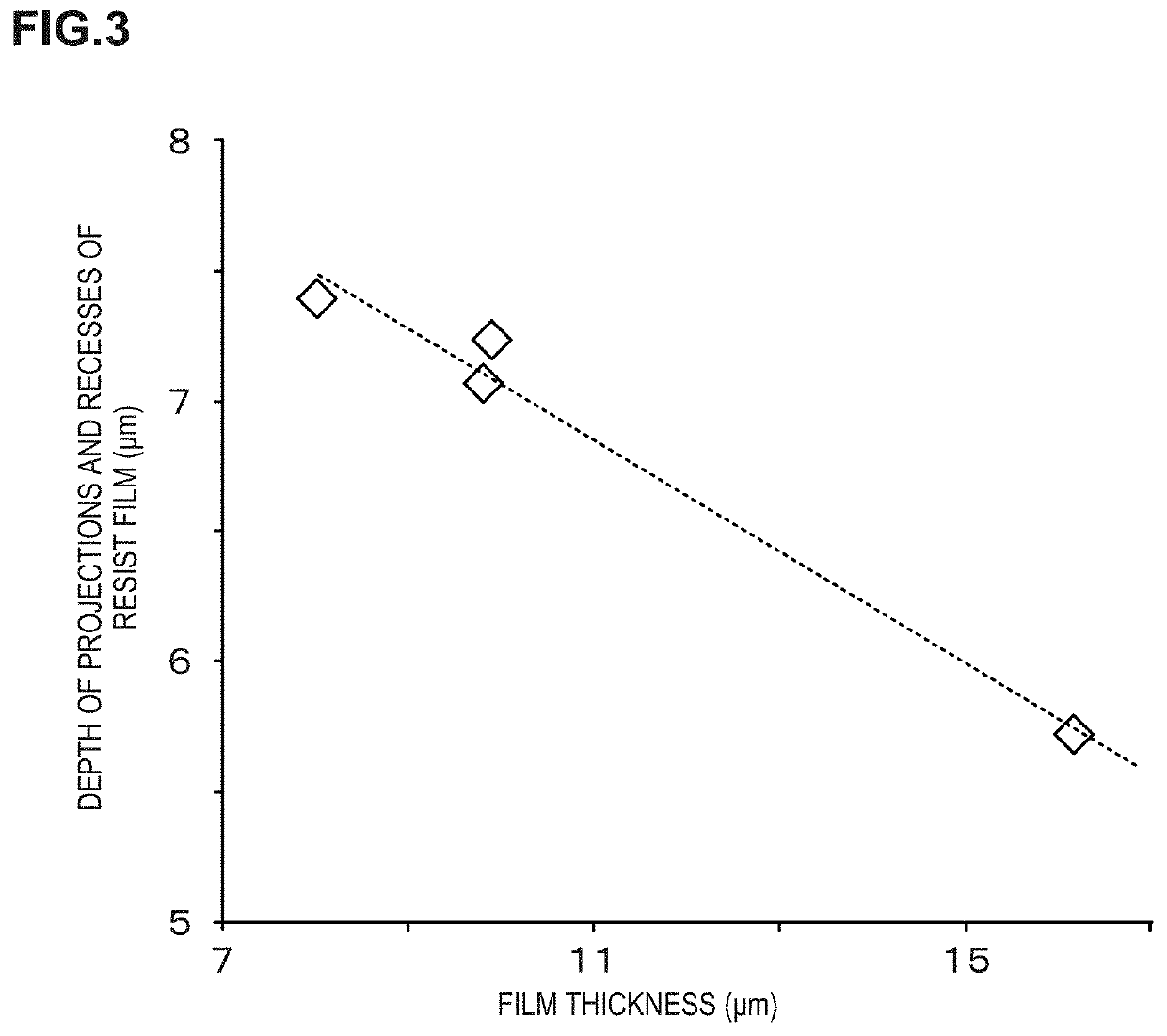
Using the technique disclosed in Japanese Patent Application Laid-open No. 2014-165252 can reduce the projections and recesses on the surface of the resist film R but cannot improve the uniformity of the film thickness of the resist film R. Further, in the case where the projections and recesses on the orders as those on the wafer W in the manufacturing process of the 3D-NAND semiconductor device are formed on the wafer surface, the CD of the pattern to be formed on the recessed portion N of the wafer W is more affected by in-plane nonuniformity of the film thickness of the resist film than by the projections and recesses on the surface of the resist film R on the wafer W.

Method used


Image

  • Film forming method, storage medium, and film forming system
  • Film forming method, storage medium, and film forming system
  • Film forming method, storage medium, and film forming system

Examples


first embodiment

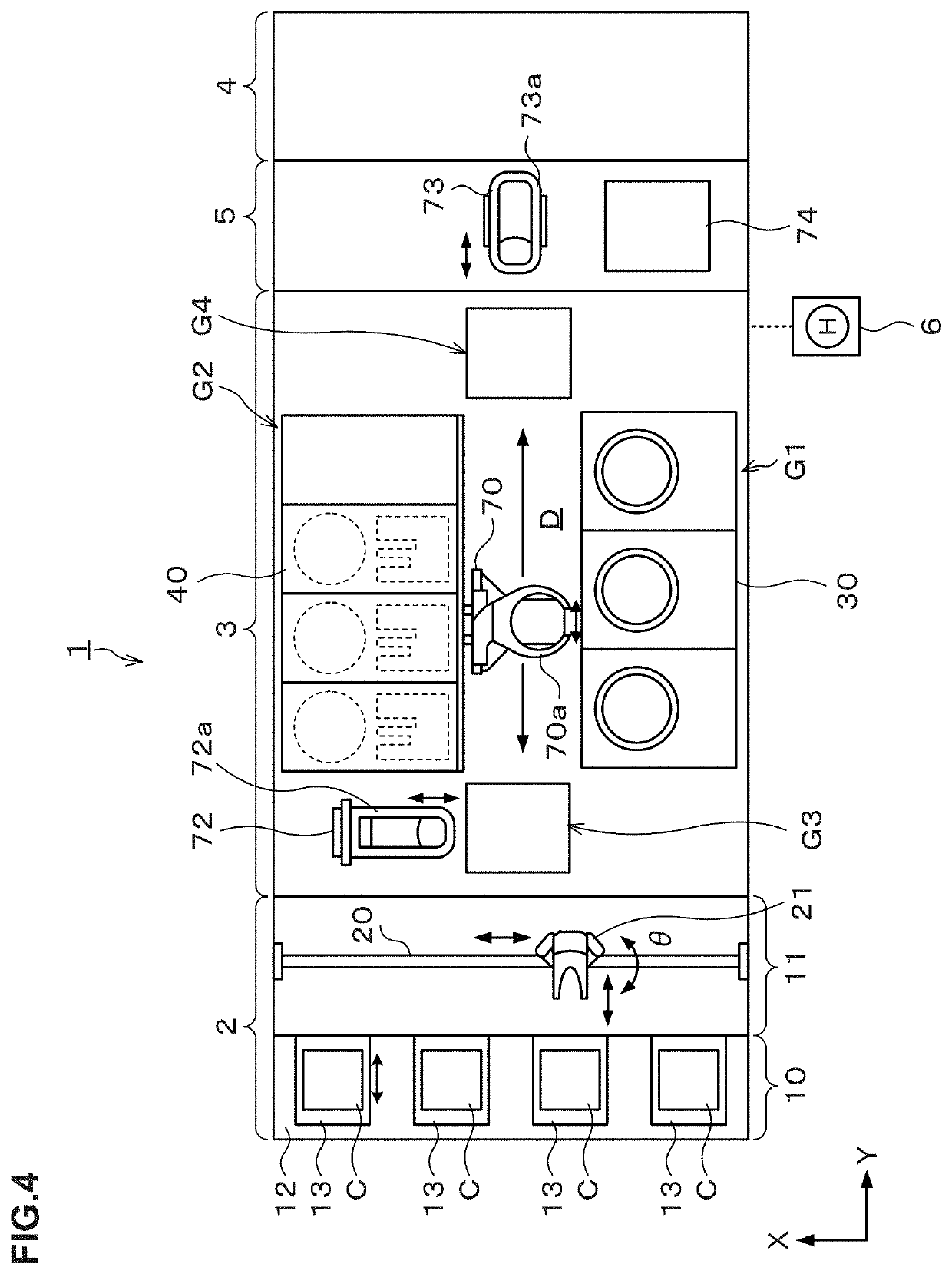
[0044]FIG. 4 is an explanatory view illustrating the outline of an internal configuration of a substrate treatment system 1 as a film forming system according to a first embodiment. FIG. 5 and FIG. 6 are a front view and a rear view illustrating the outline of the internal configuration of the film forming system 1, respectively. Note that an example where the substrate treatment system 1 applies a resist solution as a coating solution onto a wafer W as a substrate to form a resist film as a coating film will be described in the following. Further, a predetermined pattern of a silicon oxide film (SiO2 film) or the like is layered in advance on a surface of the wafer to be treated in the film forming system 1, and projections and recesses as described using FIG. 17, namely, projections and recesses in which the projecting portion and the recessed portion are large in width and the recessed portion is low in aspect ratio (ratio of the depth of the recessed portion to the width of the ...

second embodiment

[0098]Though the acid treatment is performed as the surface treatment of modifying the upper portion of the thick film into a state of being soluble in the developing solution in the above first embodiment, this embodiment is to perform ultraviolet irradiation processing as the surface treatment.

[0099]FIG. 12 and FIG. 13 are a front view and a rear view illustrating the outline of an internal configuration of a substrate treatment system 1 as a film forming system according to a second embodiment of the present invention, respectively. A plan view of this substrate treatment system is the same as that in FIG. 4 and is thus omitted.

[0100]The substrate treatment system 1 in FIG. 12 and FIG. 13 does not include the acid treatment apparatuses 32 in the first block G1 but includes ultraviolet processing apparatuses 42 instead as the surface treatment apparatuses in the second block G2, unlike the substrate treatment system in FIG. 4 to FIG. 6.

[0101]FIG. 14 and FIG. 15 are a longitudinal ...


PUM

PropertyMeasurementUnit
depthaaaaaaaaaa
depthaaaaaaaaaa
depthaaaaaaaaaa

Abstract

A film forming method for forming a coating film by applying a coating solution onto a substrate having projections and recesses formed on a surface thereof by a predetermined pattern, includes: applying the coating solution onto the surface of the substrate to form a thick film having a depth of projections and recesses on a surface of the film of a predetermined value or less and having a film thickness larger than a target film thickness of the coating film; and removing the surface of the thick film to form the coating film having the target film thickness.

Description

CROSS REFERENCE TO RELATED APPLICATIONS[0001]This application is based upon and claims the benefit of priority of the prior Japanese Patent Application No. 2017-119627, filed in Japan on Jun. 19, 2017, the entire contents of which are incorporated herein by reference.BACKGROUND OF THE INVENTION1. Field of the Invention[0002]The present invention relates to a film forming method, a storage medium, and a film forming system for forming a coating film by applying a coating solution onto a substrate having projections and recesses formed on a surface thereof by a predetermined pattern.2. Description of the Related Art[0003]In a photolithography step in a manufacturing process of a semiconductor device in a multilayer structure, a coating treatment of applying a coating solution, for example, onto a semiconductor wafer (hereinafter, referred to as a “wafer”) to form a resist film or the like, exposure processing of exposing the resist film to a predetermined pattern, a developing treatme...

Claims


Application Information

Patent Timeline
Patent Type & Authority Patents(United States)
IPC IPC(8): B05D3/10B05D3/06B05D1/00B05C5/00H01L51/00H01L21/027H01L21/3105H10K99/00
CPCB05D3/107B05C5/002B05D1/005B05D3/065H01L21/0273H01L21/31058H01L51/00H01L51/0018G03F7/16H01L21/0271H01L21/6715H10K77/00H10K71/233H01L21/02282H01L21/02307H01L21/67017H10K99/00
Inventor YOSHIHARA, KENTAROYOSHIDA, YUICHISHIBATA, NAOKIYOSHIHARA, KOUSUKE
Owner TOKYO ELECTRON LTD
Learn More