
Systems and methods for integrated welding of metal materials

a welding system and metal material technology, applied in the field of integrated welding methods, can solve the problems of exposing the bare metal surface of the workpiece, forming melting clusters, and creating deformation structures within the weld nugget, and achieve the effect of efficient bonding similar

Active Publication Date: 2021-01-12
FARADAY&FUTURE INC
View PDF4 Cites 0 Cited by
  • Summary
  • Abstract
  • Description
  • Claims
  • Application Information

AI Technical Summary

Benefits of technology

The present invention is an integrated welding system and method that can efficiently bond similar and dissimilar metal materials with associated apparatuses. The method utilizes ultrasonic vibration and electrical resistance heating, which breaks down oxide films at the interface to expose bare metal surfaces, allowing for better bonding. The ultrasonic vibration can also create deformation structures within the weld nugget, improving microstructural and mechanical properties like bond strength, texture, and grain structure. The method can reduce porosity, dynamic / static recrystallization, and cracks in the welded material. Overall, the method overcomes shortcomings of conventional welding techniques and ensures better quality welds.

Problems solved by technology

The ultrasonic vibration can breakdown the oxide film at the interface, exposing bare metal surfaces of the workpieces.
The heat can cause melting clusters to form.
Further, solidification stopped, application of further vibration results in creating deformation structure within the weld nugget, which is an area of a joint where two pieces of metals are welded together.
Additionally, the integrated welding method can create vacancies, at atomic scale, in the materials of the workpieces, which can accelerate melting process due to collapse of melting point and further lower the required power for the welding process.

Method used


Image

  • Systems and methods for integrated welding of metal materials
  • Systems and methods for integrated welding of metal materials
  • Systems and methods for integrated welding of metal materials

Examples


Embodiment Construction

[0042]The embodiments of the present invention include an integrated welding system and method for operation thereof. The integrated welding system can efficiently bonding similar and dissimilar metal materials and associated apparatuses.

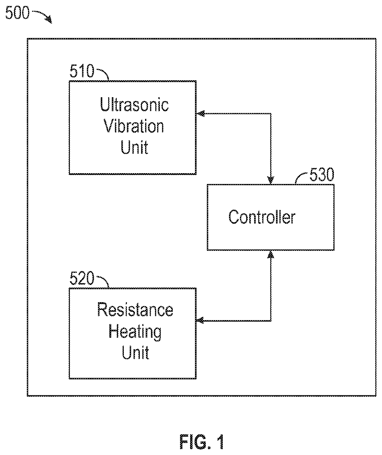
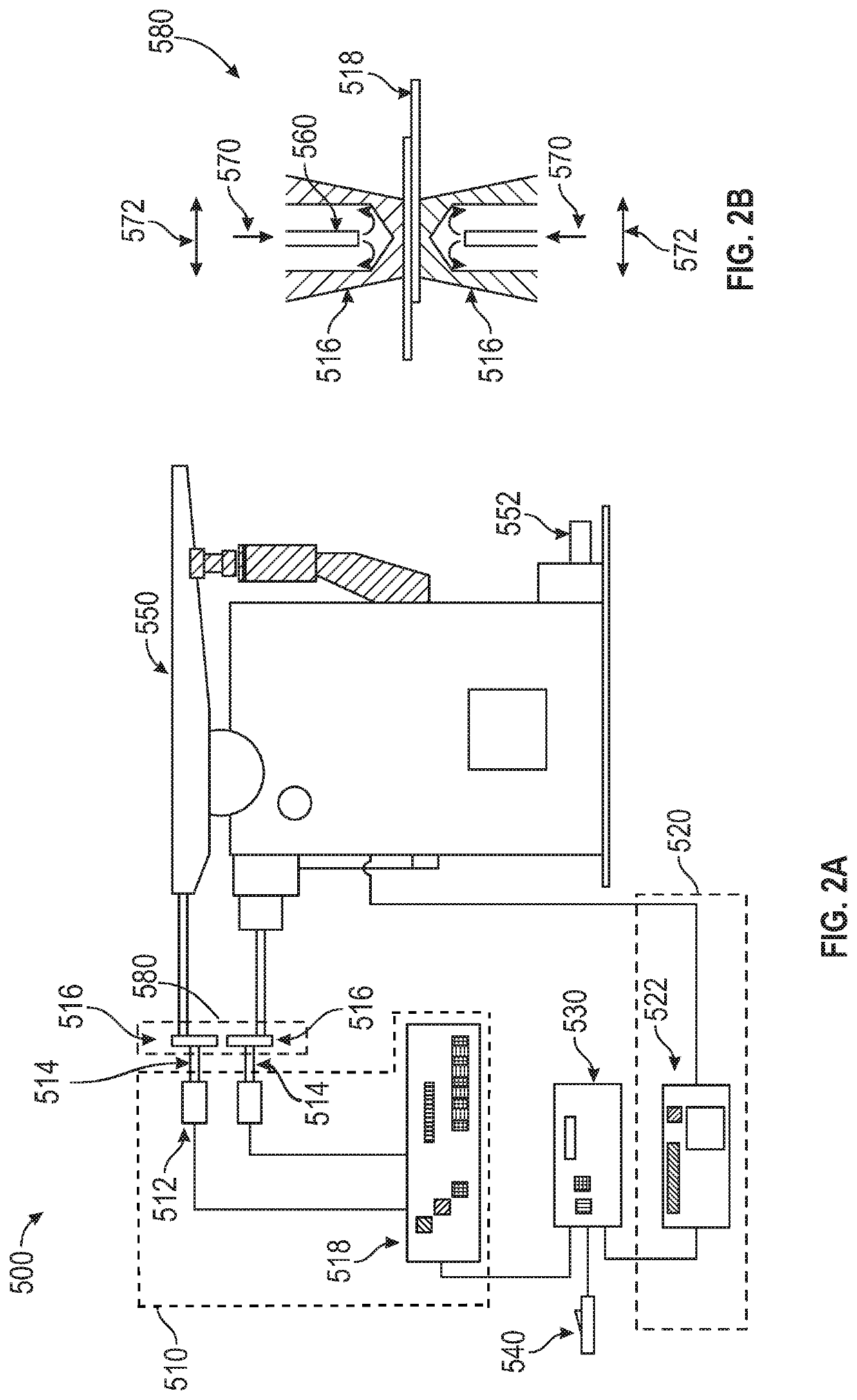
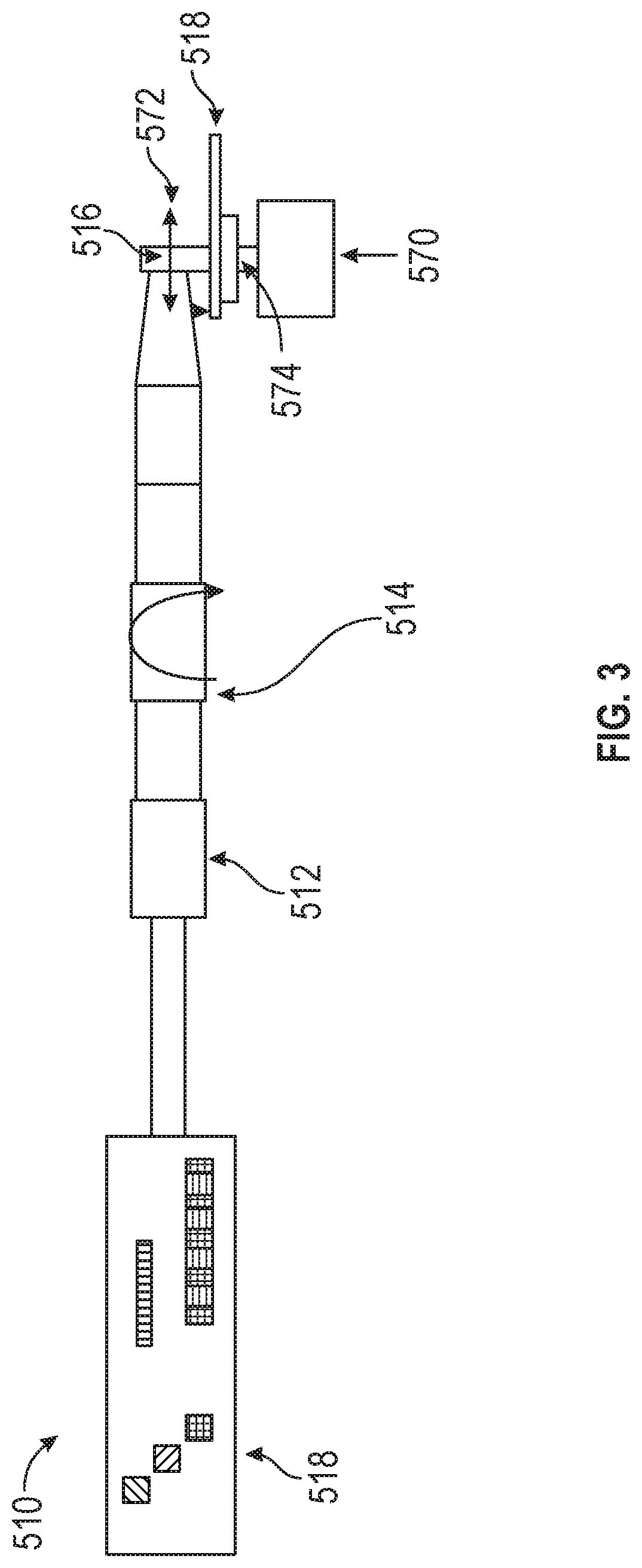
[0043]The integrated welding system can include an ultrasonic vibration unit, a resistance heating unit, and a controller. The ultrasonic vibration unit 510 is configured to create and apply an ultrasonic vibration to the workpieces, where the vibration may facilitate the breakdown of any oxide film located between the interfaces of the workpieces. The resistance heating unit 520 is configured to heat up the workpieces by way of an applied electric current. The controller 530 may control the ultrasonic vibration unit 510 and the resistance heating unit 520 for operation of the integrated welding system.

[0044]The disclosed integrated welding method can employ both ultrasonic vibration (e.g., friction) heating and electrical resistance heating. The ul...


PUM

PropertyMeasurementUnit
frequencyaaaaaaaaaa
frequencyaaaaaaaaaa
axial forceaaaaaaaaaa

Abstract

A method for welding multiple workpieces together includes applying a force to the multiple workpieces, generating ultrasonic vibration, transferring the ultrasonic vibration to the multiple workpieces to breakdown an oxide layer, generating an electric current, transmitting the electric current to heat up the workpieces, and synchronizing the ultrasonic and resistance heating operations. A welding system includes an ultrasonic vibration unit that generates an ultrasonic vibration and transfers the ultrasonic vibration to multiple workpieces to breakdown an oxide layer, a resistance heating unit that generates an electric current and transmits the electric current to heat up the workpieces, a workpiece mount that includes electrodes configured to receive the generated current and / or clamp the multiple workpieces during a welding process, and a controller configured to synchronize an operation of the ultrasonic vibration unit and an operation of a resistance heating unit.

Description

CROSS-REFERENCE TO RELATED APPLICATIONS[0001]This application claims priority to U.S. Provisional Patent Application No. 62 / 606,127, filed on Oct. 9, 2017 and titled “Welding Apparatus and Method,” which is hereby incorporated by reference in its entirety.FIELD OF THE DISCLOSURE[0002]This disclosure relates generally to welding, and more particularly, to an integrated welding method and associated apparatuses.BACKGROUND OF THE DISCLOSURE[0003]There are multiple ways for welding two materials together. Two ways are resistance spot welding (RSW) and ultrasonic spot welding (USW), both having challenges and associated compromises for welding similar and dissimilar materials and large-sized workpieces.[0004]RSW is a technique for joining thin gauge sheets used in various manufacturing applications including automotive, aerospace, and packaging. The RSW process begins by clamping workpieces between water-cooled copper electrodes. Axial forces are loaded and an electric current is applied...

Claims


Application Information

Patent Timeline
Patent Type & Authority Patents(United States)
IPC IPC(8): B23K11/12B23K11/11B23K11/24B23K11/30
CPCB23K11/12B23K11/11B23K11/24B23K11/241B23K11/3018B23K20/10B23K11/115B23K11/0026B23K11/166B23K11/18B23K2101/006B23K2101/18B23K2101/34B23K2103/04B23K2103/15B23K2103/10B23K28/02B23K11/314B23K11/36B23K20/106B23K11/34B23K2103/18
Inventor HADDADI, FARIDMERCADO-PEREZ, ANTONIOBETHELL, PHILIP ANTONIO REID
Owner FARADAY&FUTURE INC
Learn More