Tantalum sputtering target

a sputtering target and sputtering technology, applied in the direction of vacuum evaporation coating, electric discharge tube, coating, etc., can solve the problems of difficult to uniformly deposit a sputtering substance onto a wafer surface, difficult to control the direction of the substance emitted from the target, etc., to achieve the effect of improving the uniformity of film thickness

Active Publication Date: 2021-11-16
JX NIPPON MINING & METALS CORP
View PDF33 Cites 0 Cited by
  • Summary
  • Abstract
  • Description
  • Claims
  • Application Information

AI Technical Summary

Benefits of technology

[0041]The use of the tantalum sputtering target according to the present invention can allow improvement of film thickness uniformity during a high-power sputtering. Therefore, the tantalum sputtering target according to the present invention is particularly advantageous for application of forming a barrier seed layer corresponding to a fine Cu wiring pattern.

Problems solved by technology

However, the high power sputtering is difficult to control the direction of substance emitted from a target, and is also difficult to uniformly deposit a sputtering substance onto a wafer surface as the wires of the semiconductor integrated circuit is increasingly miniaturized.
The problems are remarkable particularly when embedding is carried out in a wire hole having a large aspect ratio.

Method used


Image

  • Tantalum sputtering target
  • Tantalum sputtering target

Examples


example 1

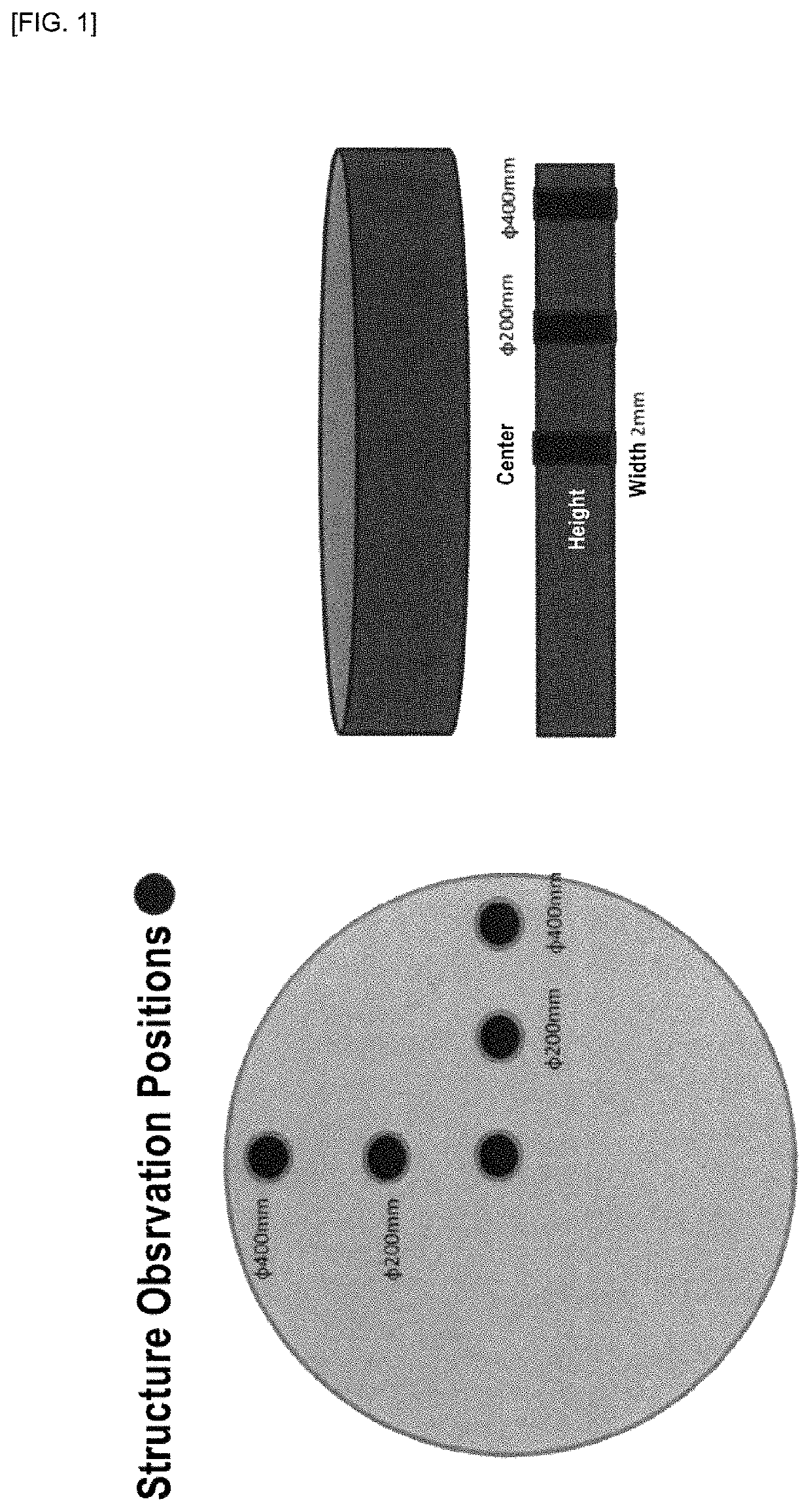
[0083]A tantalum raw material having a purity of 99.997% by mass was melted by electron beam and cast to prepare an ingot having a length of 1000 mm and a diameter of φ195 mm. This ingot was then subjected to cold press forging to have a diameter of φ150 mm, and then cut at a required length to obtain a billet. The billet was then subjected to a heat treatment at a temperature of 1250° C., followed by a primary cold forging, a heat treatment at 1000° C., and a secondary cold forging. The billet was then split into two parts and subjected to a heat treatment at 1000° C. again.

[0084]The forged billet was then subjected to cold cross rolling. The cross rolling was carried out by repeating a total 10 sets of cross rolling at a rolling reduction of less than 12% per one pass and then performing cold rolling with a reduction ratio of less than 10% per rolling pass. The rolled material after the cold rolling was subjected to a heat treatment at 800° C. The resulting target material having ...

examples 2 to 7

[0085]Disc-shaped tantalum sputtering targets each having a thickness of 6.35 mm and φ450 mm were produced in the same procedure as that of Example 1, with the exception that a final cold rolling was carried out between the heat treatment at 800° C. and the finishing machining under the conditions of the total rolling reduction and the rolling reduction per one pass as shown in Table 1. It should be noted that the final pass during the final cold rolling was smaller than the one pass condition shown in Table 1, because fractions were adjusted in the final pass.

(Purity)

[0086]The tantalum sputtering targets of the respective test examples obtained by the above producing method were sampled and subjected to compositional analysis by means of glow discharge mass spectrometry (GDMS), demonstrating that all the tantalum sputtering targets according to the test examples had a purity of 99.995 by mass or more.

(Average Value of Vickers Hardness)

[0087]For the tantalum sputtering target of eac...


PUM

PropertyMeasurementUnit
aspect ratiosaaaaaaaaaa
grain diameteraaaaaaaaaa
aspect ratiosaaaaaaaaaa

Abstract

Provided is a tantalum sputtering target that contributes to improvement of film thickness uniformity during a high-power sputtering. A tantalum sputtering target having a purity of 99.99% by mass or more and an average value of Vickers hardness on a sputtering surface of from 85 to 110 Hv, the tantalum sputtering target satisfying both of the following conditions (1) and (2):(1) when a cross section perpendicular to the sputtering surface is measured by EBSP, an average value of Kernel Average Misorientation values (KAM values) is from 0.2° to 2.8°; and(2) when a cross section perpendicular to the sputtering surface is measured by EBSP, an average value of orientation area ratios of a {100} plane oriented at a misorientation of within 15° relative to a normal direction of the sputtering surface is 20% or more.

Description

TECHNICAL FIELD[0001]The present invention relates to a tantalum sputtering target.BACKGROUND ART[0002]In many fields such as an electronics field, a corrosion-resistant material and decoration fields, a catalyst field, and production of cutting / abrasive materials and wear-resistant materials, a sputtering method for forming a film of a metal or a ceramics material or the like is employed. The sputtering method itself is well known in the above fields. Recently, the electronics field particularly requires a tantalum sputtering target suitable for forming a coated film having a complex shape and forming a circuit, in particular for forming a barrier seed layer that covers wires for a semiconductor integrated circuit.[0003]Recently, high power sputtering using a magnetron sputtering apparatus is performed in order to increase a film deposition rate of sputtering. However, the high power sputtering is difficult to control the direction of substance emitted from a target, and is also di...

Claims


Application Information

Patent Timeline
Patent Type & Authority Patents(United States)
IPC IPC(8): H01J37/34C23C14/34C22C27/02C22C45/10
CPCH01J37/3426C22C27/02C22C45/10C23C14/3414
Inventor NAGATSU, KOTARO
Owner JX NIPPON MINING & METALS CORP
Why Eureka
Try Eureka