Method and apparatus for mechanical transmyocardial revascularization of the heart

a technology heart muscle, which is applied in the field of mechanical transmyocardial revascularization of the heart, can solve the problems of large and expensive laser equipment for performing such procedures, inaccessibility to many patients, and difficulty in obtaining the techniqu

Inactive Publication Date: 2001-05-10
MUELLER RICHARD L
View PDF0 Cites 17 Cited by
  • Summary
  • Abstract
  • Description
  • Claims
  • Application Information

AI Technical Summary

Benefits of technology

10. More specifically, an advantage of the present invention to provide an apparatus and method for mechanically performing TMR without excessive tearing or other complications which cause blockage of the created channels.
11. It is a further advantage of the present invention to provide an apparatus and method for mechanically performing TMR without a requirement for large, expensive equipment.
14. The present invention comprises a method and apparatus for mechanically performing transmyocardial revascularization (TMR). Although the invention may be implemented in a variety of embodiments, several of which are illustrated herein, all require an apparatus with a special cutting tip assembly, preferably an easily removable cutting tip assembly which would allow rapid replacement to permit several channels to be created in a relatively short period of time. This cutting tip assembly has means for supporting the assembly in location on the heart wall while in operation. In several of the embodiments shown herein, the support means may include suction to assist in clean, complete removal of the material excised from the heart wall by the cutting tip assembly during formation of channels. In all embodiments there also is a mechanical means present to remove that material which is to be excised to form the channel. Preferably, the cutting tip assembly is removably mounted to a hand piece with an actuator to deploy, rotate, and remove the cutting tip assembly. The hand tool may accommodate one or more cutting tip assemblies.
15. The cutting tip assembly optionally may be heated to provide thermal damage to the heart muscle during the creation of the channel, providing some of the advantage of the laser method of TMR. Such heating may be provided by placing the cutting tip assembly in a specially designed heater base which permits rapid connection of the assembly to the remainder of the apparatus while the cutting tip assembly is still in the heater. In this way the cutting tip assembly may be maintained at optimal temperature until the apparatus is ready to be deployed.

Problems solved by technology

2. Heart disease is a significant health problem which has been the subject of substantial medical study.
Bypass surgery has become commonplace; yet such surgery may be unavailable to many patients, either because of the nature of the occlusions or the physical condition of the patient.
5. Unfortunately, this technique has some attendant difficulties.
The laser equipment for performing such procedures is large and expensive and may be unavailable to smaller and more remote medical facilities.
Some patients may therefore find it difficult to gain access to a properly equipped medical facility when treatment is needed.
Unfortunately, as noted in the Aita et al. patent, prior art methods of mechanical piercing and cutting of the heart wall produce tearing of the tissue.
Such tearing leads to fibrosis, which combined with the problems of maintaining clear, clean channels, seriously diminishes the effectiveness of the TMR treatment produced by such methods.
Hence, such prior art mechanical piercing does not adequately facilitate rapid and clean healing of channels.
7. Another alternative approach, melting of the myocardium by hot probes, has proven unsatisfactory, partly because there is no mechanism for removal of melted material from the channel.

Method used


Image

  • Method and apparatus for mechanical transmyocardial revascularization of the heart
  • Method and apparatus for mechanical transmyocardial revascularization of the heart
  • Method and apparatus for mechanical transmyocardial revascularization of the heart

Examples


Embodiment Construction

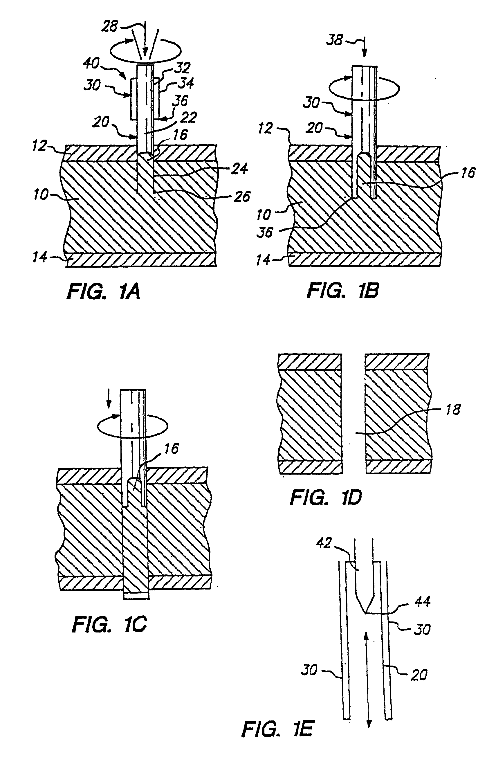
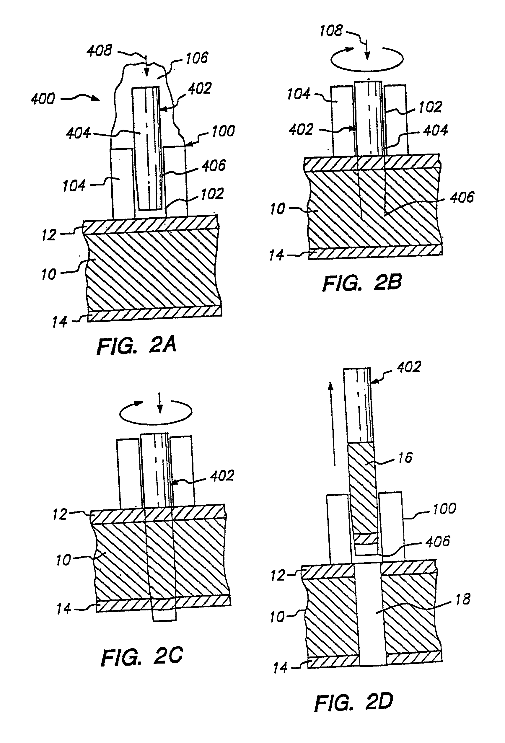
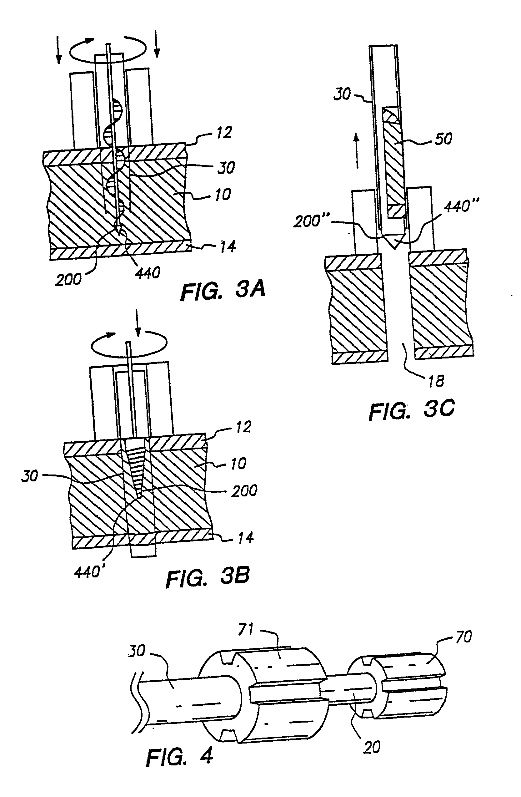
24. While a variety of embodiments of the present invention are disclosed herein, one exemplary presently preferred embodiment is illustrated in FIGS. 1A through 1D. FIGS. 1A through 1D each represent a different stage in the process of creating a channel 18 in the myocardium 10, which has an outer wall (epicardium) 12 and an inner wall (endocardium) 14.

25. FIG. 1A illustrates that the apparatus of this embodiment of the present invention has a cutting tip assembly 40 with an inner cylindrical needle 20, which has a tubular hollow internal bore 22 within its body 24. Because inner needle 20 is cylindrical, it has a lateral axis 28. Inner needle 20 has a sharpened edge 26, which may be made sharp through use of a variety of geometries (e.g., beveled inward, beveled outward). A presently preferred cutting edge defines an angle less than 45 degrees, and preferably less than 30 degrees, from the lateral axis 28. The cutting edge is sharpened using conventional techniques used in, for in...


PUM


Abstract

An apparatus for creating revascularization channels in tissue, such as the myocardium of the heart, mechanically cuts the channels using a hand piece with easily removable cutting tip assemblies having angled, sharpened edges to allow rapid tip replacement. The cutting tip assembly has an inner needle within an outer hollow needle with each needle attached to the hand piece for independent rotation and axial movement. The inner needle may be hollow, or formed with a pointed tip, and may rotate counter to the outer needle to enhance gripping and storage of the tissue excised by the outer needle. The hand piece may attach a cylindrical magazine of cutting tip assemblies or one cutting tip assembly. The cutting tip assembly may be heated to provide thermal damage to the heart muscle during the creation of the channel, providing some of the advantages of the laser method of TMR.

Description

1. This invention relates to the field of surgical interventions for correction of coronary disease, and more particularly to the methods and devices for transmyocardial revascularization of the heart.2. Heart disease is a significant health problem which has been the subject of substantial medical study. Bypass surgery has become commonplace; yet such surgery may be unavailable to many patients, either because of the nature of the occlusions or the physical condition of the patient.3. One promising alternative technique for treating such cases is known as trans-myocardial revascularization (TMR). Although this technique was considered as early as the work of Dr. C. Beck "the Development of a New Blood Supply to the Heart By Operation", Annals of Surgery, Vol. 102, No. 5 (11 / 35) pp. 801-813, the method was not extensively studied until the work of Dr. M. Mirhoseini and M. Cayton, an example of which is found in "Lasers in Cardiothoracic Surgery in Lasers in General Surgery (Williams...

Claims


Application Information

Patent Timeline
Patent Type & Authority Applications(United States)
IPC IPC(8): A61B10/00A61B10/02A61B17/34A61B10/04A61B17/00A61B17/30A61B17/32
CPCA61B10/0275A61B10/04A61B17/320016A61B17/32002A61B17/32053A61B2010/0208A61B2017/00247A61B2017/00292A61B2017/306A61B2018/00392
Inventor MUELLER, RICHARD L.
Owner MUELLER RICHARD L
Why Eureka
Try Eureka