Magnetic recording medium

a magnetic recording and recording medium technology, applied in the field of qmd, can solve the problems of difficulty in retaining written information, difficulty in reversing the magnetization direction of a specific crystal grain, etc., and achieve the effects of eliminating magnetic interference, stabilizing the magnetization of the hard magnetic layer 8, and eliminating the cancellation of the magnetization of neighboring hard magnetic components

Inactive Publication Date: 2001-07-05
FUJI ELECTRIC CO LTD
View PDF0 Cites 27 Cited by
  • Summary
  • Abstract
  • Description
  • Claims
  • Application Information

AI Technical Summary

Benefits of technology

0063] Referring now to FIG. 9(a), a typical illustration in cross section of the first magnetic recording medium of FIGS. 1(a)-1(c). FIG. 9(b) is a typical illustration in cross section of a conventional magnetic recording medium containing a single layer of a hard magnetic layer 8. Arrows in the figures denote the direction of magnetization recorded, that is, magnetized in the indicated direction of each magnetic component. In a conventional magnetic recording medium, the magnetic field of a magnetic component permeates through a non-magnetic isolating component 6. As a consequence, the attempt to isolate hard magnetic components 8 using isolating components 6 in the conventional magnetic recording medium does not

Problems solved by technology

Reducing crystal grain diameter, however, causes difficulty in retaining written information (the magnetization direction) when the crystal grains are subject to disturbance caused by thermal oscillation.
Intense interaction among magneti

Method used


Image

  • Magnetic recording medium
  • Magnetic recording medium
  • Magnetic recording medium

Examples


example 2

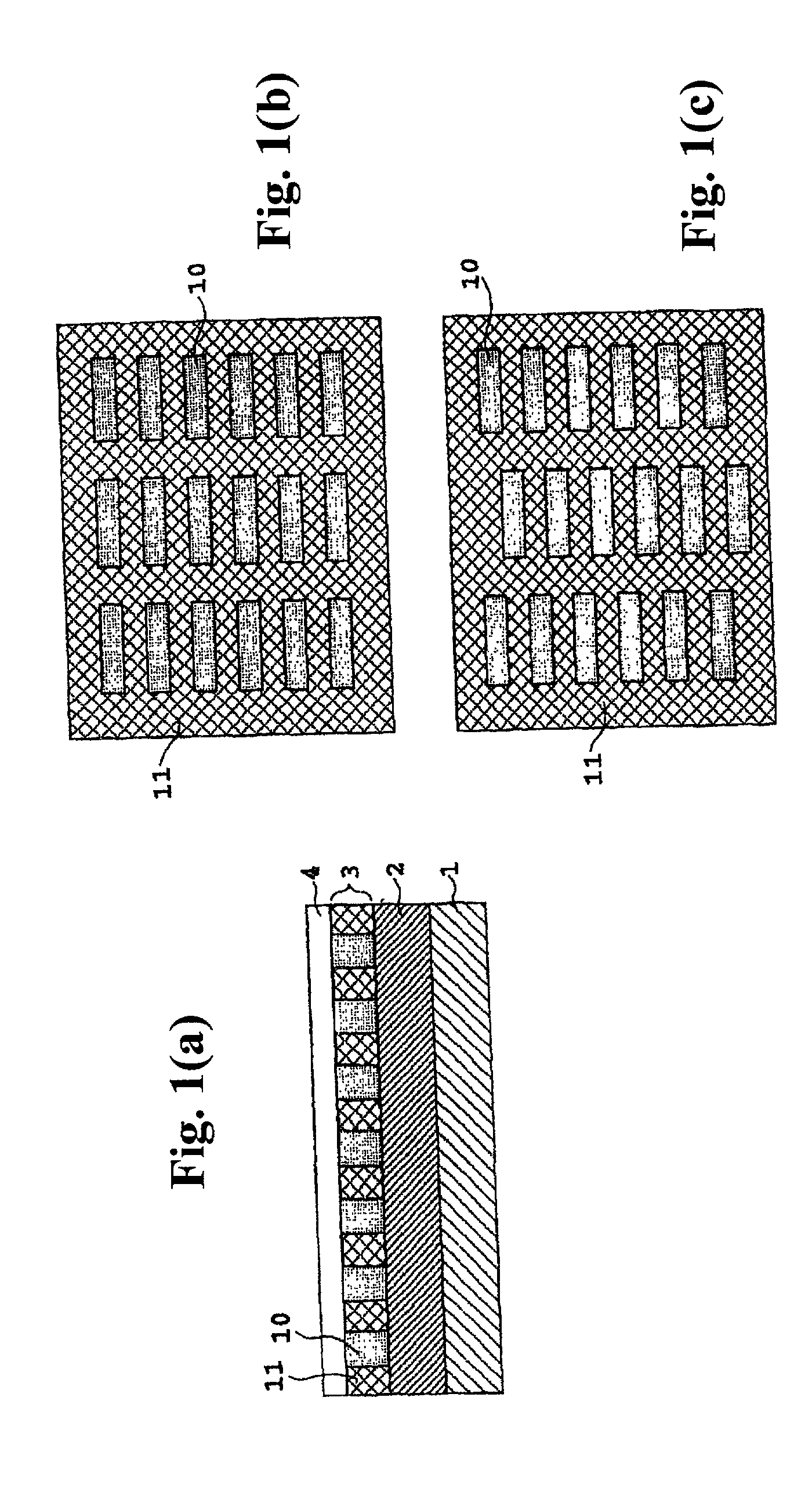
[0073] A first magnetic recording medium shown in FIGS. 2(a)-2(c) was manufactured in the same way as in example 1, except that a soft magnetic layer 7 was formed on top of a hard magnetic layer 8. That is, the locations of the soft magnetic layer 7 and the hard magnetic layer 8 are interchanged from example 1.

[0074] Stability in magnetization of the medium was studied in the same way as that in example 1 to find that the medium in example 2 reverses magnetization at a magnetic field of some 3500 Oe.

example 3

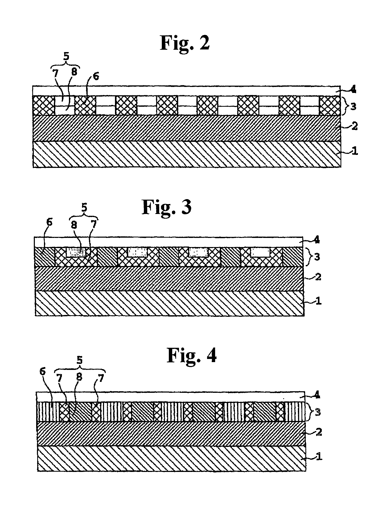
[0075] A third of a first magnetic recording medium shown in FIG. 3 was manufactured in the following way.

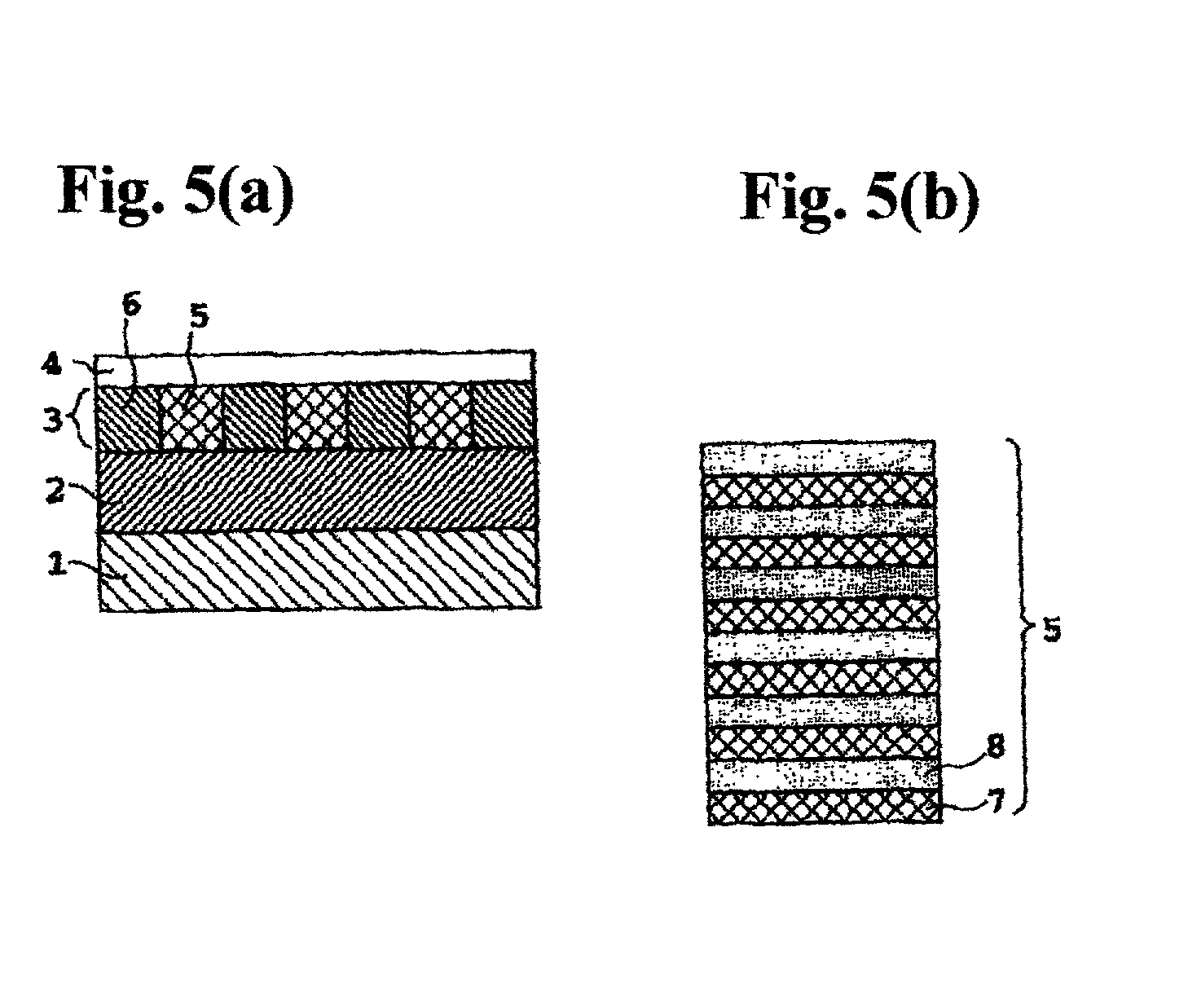
[0076] An under layer 2 was formed on a non-magnetic substrate 1. An isolating layer 6 was formed by patterning holes part way through an isolating layer 9 in the same way as that in example 1. Then, a soft magnetic layer 7 was formed higher in the holes patterned in the isolating layer 9, followed by chemomechanical polishing to give a flat surface of a medium under manufacture.

[0077] Applying poly-methylmethacrylate resin membrane, patterning with electron beam, and etching a soft magnetic layer 7 with reactive ions for the second time gives recesses into which a hard magnetic layer 8 is deposited. Finally, forming and flattening a hard magnetic component provides a magnetic recording medium shown in FIG. 3.

[0078] The stability in magnetization of the medium was studied in the same way as that in example 1 to find that the medium in example 3 reverses magnetization at a magnet...

example 4

[0079] A fourth of a first magnetic recording medium as shown in FIG. 4 was manufactured as in example 3 above except that holes leading to the under layer 2 are formed instead of forming recesses in the soft magnetic layer 7, the hard magnetic layer 8 in this example comes into contact with the under layer 2.

[0080] Stability in magnetization of the medium was studied in the same way as that in example 1 to find that the medium in example 4 reverses magnetization at a magnetic field of 3500 Oe.


PUM

PropertyMeasurementUnit
Forceaaaaaaaaaa
Soft magnetismaaaaaaaaaa
Magnetismaaaaaaaaaa

Abstract

A magnetic recording medium has a non-magnetic substrate, an under layer, a magnetic layer, and a protective layer in the recited order. The magnetic layer consists of a plurality of magnetic components embedded in a pattern in an isolating component. Each magnetic component includes at least one magnetic component of large coercive force and one of a magnetic component of small coercive force. The two components abut each other. In one embodiment the two components form one or more alternating layers. In another embodiment, one of the components has a recess in its upper surface which is filled with the other component. In still another embodiment, the two components are disposed side by side passing through the isolating component.

Description

[0001] 1. Field of the Invention[0002] The present invention relates to a magnetic recording medium of a hard disk drive (hereinafter abbreviated as HDD) widely employed in the external memory of computers.[0003] 2. Prior Art[0004] At present, a magnetic recording medium used for hard disk drives has reached an areal density of 10 Gbits / in.sup.2 on an experimental basis.[0005] Referring to FIG. 10(a), a typical basic layered structure of a magnetic recording medium includes a non-magnetic substrate 1, upon which are deposited, in order, an under layer 2, tens of nanometers thick, a magnetic layer 3, from 10 to 20 nm thick, and a carbon protective layer 4, some 10 nm thick. Non-magnetic substrate 1 is typically a hard substrate made of aluminum alloy or glass, hundreds of micrometers thick. Under layer 2 is composed of pure chromium metal or a chromium alloy doped with molybdenum or tungsten. Magnetic layer 3 employs a cobalt alloy doped with chromium, nickel, tantalum, platinum etc....

Claims


Application Information

Patent Timeline
IPC IPC(8): C23C14/06C23C14/14C23C14/35G11B5/65G11B5/66G11B5/667G11B5/673G11B5/716G11B5/82H01F10/06
CPCB82Y10/00G11B5/716G11B5/743G11B5/82Y10S428/90Y10T428/24942
Inventor SAITO, AKIRA
Owner FUJI ELECTRIC CO LTD
Why Eureka
Try Eureka