Magnetic recording medium and manufacturing method for the same

a technology of magnetic recording medium and manufacturing method, which is applied in the field of magnetic recording medium, can solve the problems of deteriorating the resistance of the medium to friction and wear, and achieve the effect of excellent magnetic property, superior durability and electromagnetic transformation characteristi

Inactive Publication Date: 2001-09-20
FUJI ELECTRIC CO LTD
View PDF0 Cites 4 Cited by
  • Summary
  • Abstract
  • Description
  • Claims
  • Application Information

AI Technical Summary

Benefits of technology

0005] An object of the present invention is to provide a magnetic recording medium utilizing a plastic substrate, the medium exhibiting excellent magnetic prope...

Problems solved by technology

The cobalt atoms, precipitated on the medium surface, decompose the molecules of the liquid lub...

Method used


Image

  • Magnetic recording medium and manufacturing method for the same
  • Magnetic recording medium and manufacturing method for the same
  • Magnetic recording medium and manufacturing method for the same

Examples


example 2

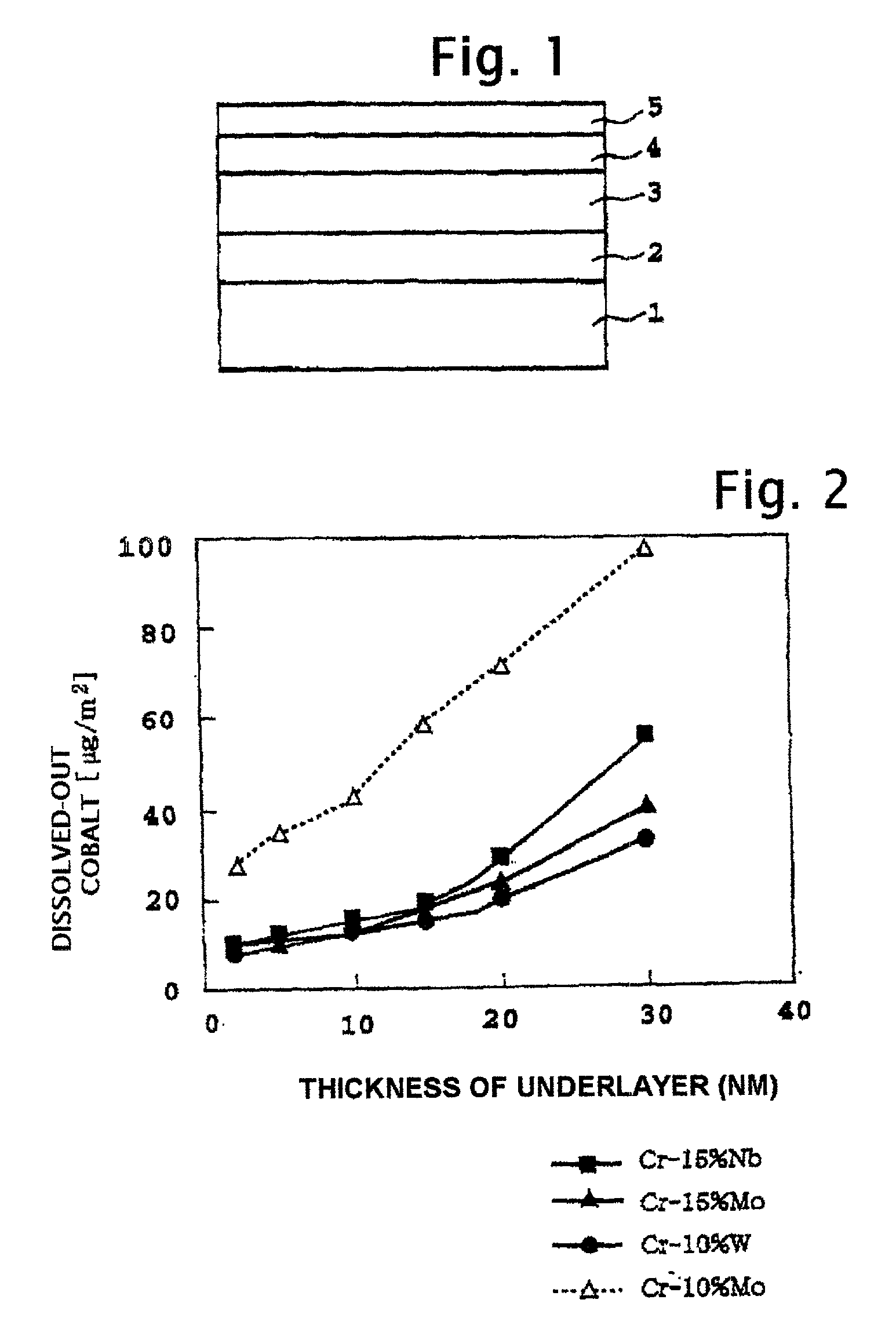
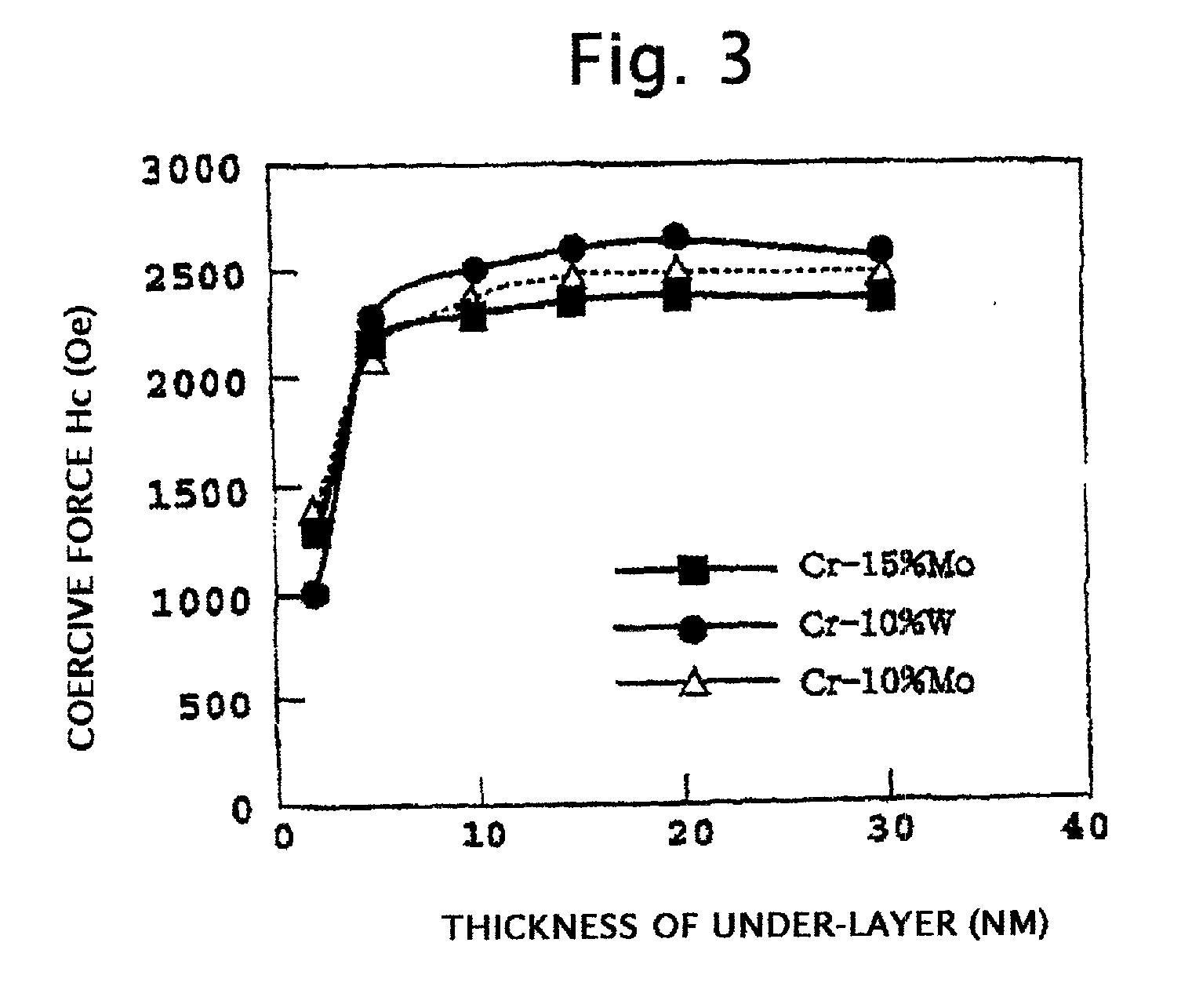
[0052] A series of magnetic recording media having the basic structure of FIG. 1 comprising under-layers composed of Cr-15 at % Nb, Cr-15 at % Mo, and Cr-10 at % W were fabricated. The thickness of the under-layer of each of the compositions was varied in the range from 2 nm to 30 nm. The sputtering process for depositing the under-layer was conducted under an argon gas pressure of 25 mTorr. Other materials and processes were the same as in Example 1.

[0053] Measurement of the quantity of dissolved-out cobalt was made in the same way as in Example 1 for each of the obtained media after exposure to a high temperature and humidity environment of 85.degree. C. and 80% relative humidity for 96 hours. The results are shown in FIG. 2.

[0054] Measurement of coercive force Hc was made for each of the obtained media by means of VSM (vibrating sample magnetometer). The results are shown in FIG. 3.

example 3

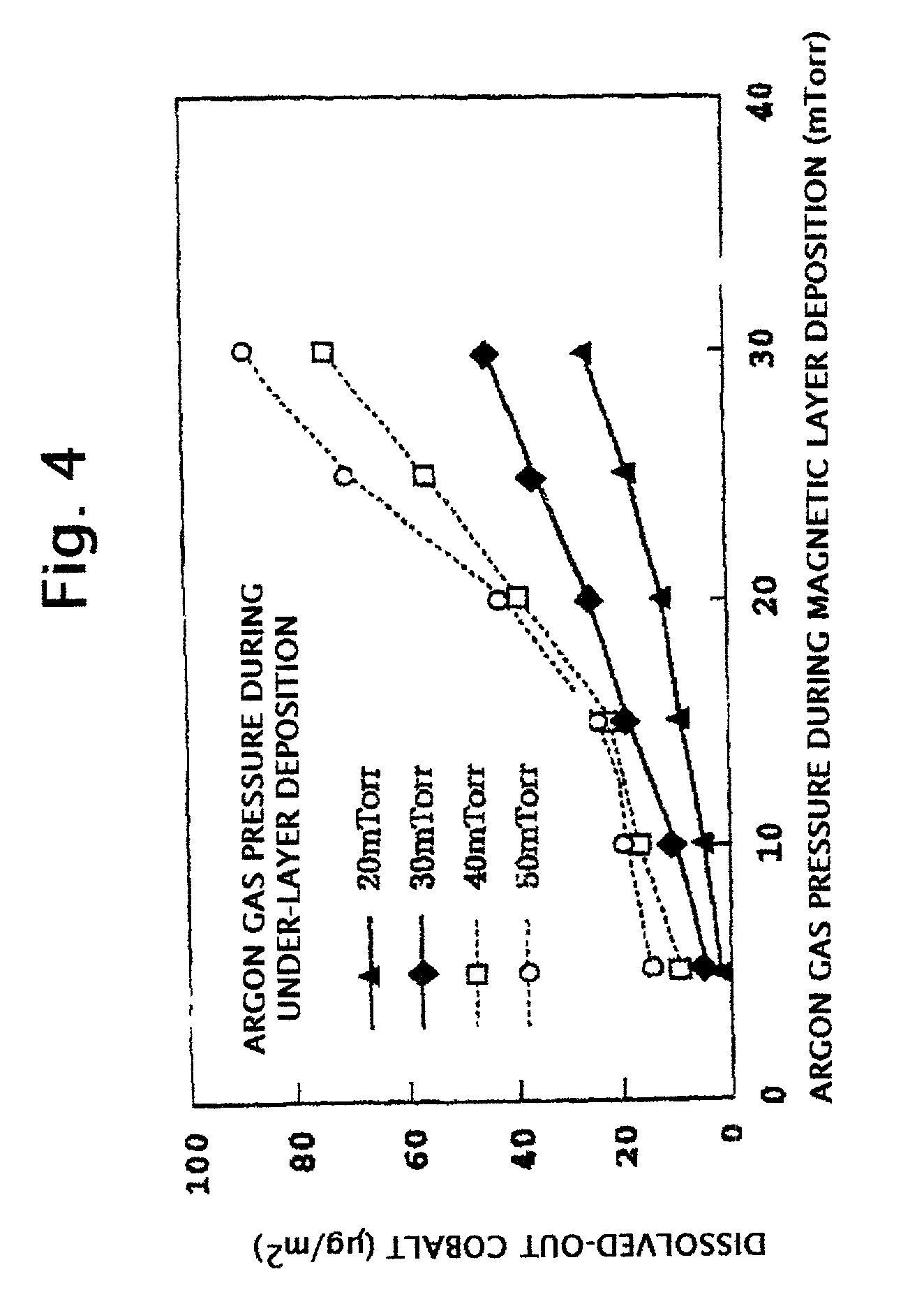
[0060] A series of magnetic recording media having the basic structure of FIG. 1 and comprising the under-layer of Cr-15 at % Mo having thickness of 15 nm were fabricated in the same manner as in Example 1 except that the argon gas pressure in the process for depositing the under-layer was varied in the range from 20 mTorr to 50 mTorr, and in the process for depositing the magnetic layer in the range from 5 mTorr to 30 mTorr.

[0061] Measurement of the quantity of dissolved-out cobalt was made in the same way as in Example 1 for each of the obtained media after exposure to a high temperature and humidity environment of 85.degree. C. and 80% relative humidity for 96 hours. The results are shown in FIG. 4.

[0062] As shown in FIG. 4, the quantity of dissolved-out cobalt strongly depends on the argon gas pressure during the processes for depositing the under-layer and the magnetic layer. That is, the quantity of dissolved-out cobalt increases rapidly with increases in the argon gas pressur...


PUM

PropertyMeasurementUnit
Timeaaaaaaaaaa
Thicknessaaaaaaaaaa
Thicknessaaaaaaaaaa

Abstract

A magnetic recording medium according to the invention includes a plastic substrate, a non-magnetic under-layer on the substrate, a magnetic layer including cobalt on the under-layer, a protective film on the magnetic layer, and a liquid lubricant layer on the protective film. The under-layer is composed of a chromium alloy having a body centered cubic lattice structure, and containing at least one element selected from the group consisting of Zr, Nb, Mo, Ru and Pd in a total amount of at least 15 at %, or containing at least one element selected from the group consisting of Hf, Ta, W, Re, Pt and Au in a total amount of at least 10 at %. The amount of cobalt dissolved out of the magnetic layer is limited by performing sputtering deposition of at least the magnetic layer at low pressures of argon.

Description

[0001] The present invention relates to a magnetic recording medium installed in various magnetic recording devices including an external memory of a computer, and to a manufacturing method therefor.[0002] Non-magnetic substrates of magnetic recording media for magnetic recording devices conventionally employ an aluminum alloy substrate with electroless NiP plating or a glass substrate. So-called plastic substrates using plastic resin have been proposed for use as non-magnetic substrates of magnetic recording medium, as disclosed in Japanese Unexamined Patent Application Publication (KOKAI) No. H10-146843, for example. The plastic substrates, which can be manufactured economically and in a great mass by injection molding, are very promising for non-magnetic substrates of magnetic recording media that require further cost reduction.[0003] When the plastic substrate is utilized as a non-magnetic substrate of a magnetic recording medium, since the temperature which the plastic substrat...

Claims


Application Information

Patent Timeline
IPC IPC(8): C23C14/34G11B5/64G11B5/65G11B5/73G11B5/738G11B5/851
CPCG11B5/656G11B5/7325G11B5/851Y10S428/90Y10T428/265Y10T428/12854G11B5/7373
Inventor UWAZUMI, HIROYUKIOIKAWA, TADAAKI
Owner FUJI ELECTRIC CO LTD
Why Eureka
Try Eureka