Composite catalyst for solid polymer electrolyte type fuel cell and processes for producing the same

Inactive Publication Date: 2002-02-14
GS YUASA INT LTD
View PDF0 Cites 32 Cited by
  • Summary
  • Abstract
  • Description
  • Claims
  • Application Information

AI Technical Summary

Problems solved by technology

However, this technique has aroused a problem that when the solid polymer electrolyte type fuel cell is operated at a high current density, water floods on the surface of the catalyst layer 261 and in the pores 267 to inhibit gas diffusion, resulting in a considerably reduced output.
Especially, this problem is tend to be occurred because the reaction yields water in it.
Because of this

Method used


Image

  • Composite catalyst for solid polymer electrolyte type fuel cell and processes for producing the same
  • Composite catalyst for solid polymer electrolyte type fuel cell and processes for producing the same
  • Composite catalyst for solid polymer electrolyte type fuel cell and processes for producing the same

Examples


example 2

[0081] The composite catalyst A obtained in Example 1 was allowed to stand for 120 minutes in a mixed gas atmosphere consisting of 3% fluorine gas and 97% nitrogen gas. Thus, a treatment for partly replacing the non-fluorine atoms bonded to the carbon atoms of P(VdF-HFP) by fluorine atoms was conducted to obtain a composite catalyst B. An electrode was produced and incorporated into a single cell for fuel cells in the same manner as in Example 1, except that the commosite catalyst B was used. Thus, a cell B was obtained.

example 3

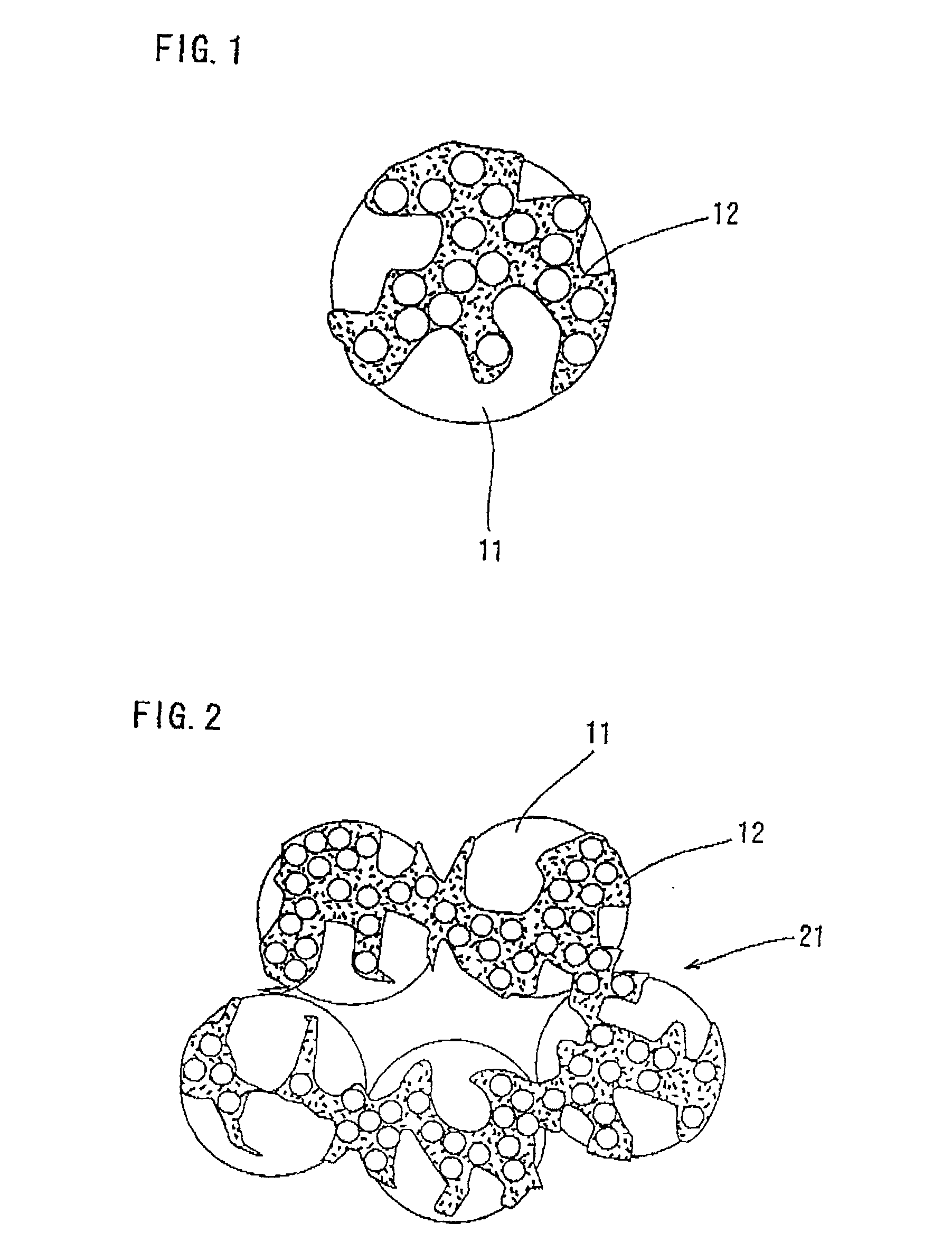
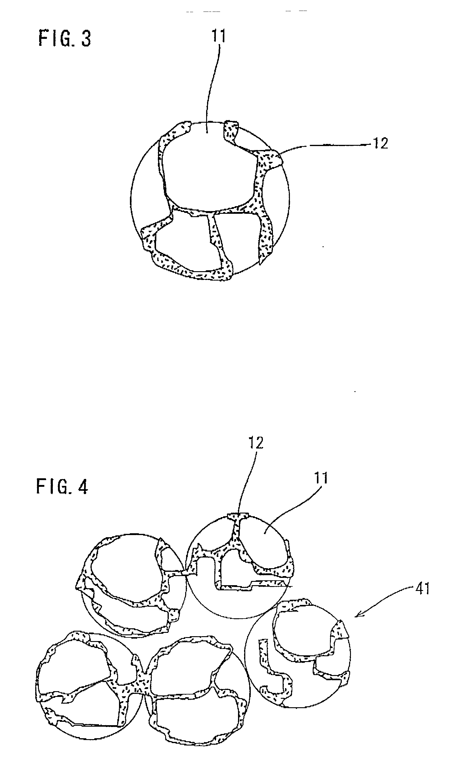
[0086] The carbon-supporting platinum (Pt / C) (10V30E, manufactured by Tanaka Kikinzoku K. K,; Valcan XC-72 having 30 wt % platinum supported thereon; average particle diameter of the carbon, 30 nm; average particle diameter of the platinum, 2.4 nm) of 7 g was mixed with 30 g of a solution (a) which was consist of a cation-exchange resin solution(5.0 wt % Nafion in a mixture of lower aliphatic alcohol and alcohol manufactured by Aldrich Inc., main solvents are ethanol)of 15 g and ethanol of 15 g. This mixture was filtered to obtain the carbon-supporting platinum having the solution (a) adherent to the surface thereof. Subsequently, this mixture was dipped into a butyl acetate as solution (b) and the resultant mixture was stirred for 1 hour. The particles were then dried to obtain a composite catalyst D consisting of the catalyst particles and the cation-exchange resin deposited on the surface thereof. After this step, the composite catalyst obtained was weighed to determine the amoun...

example 4

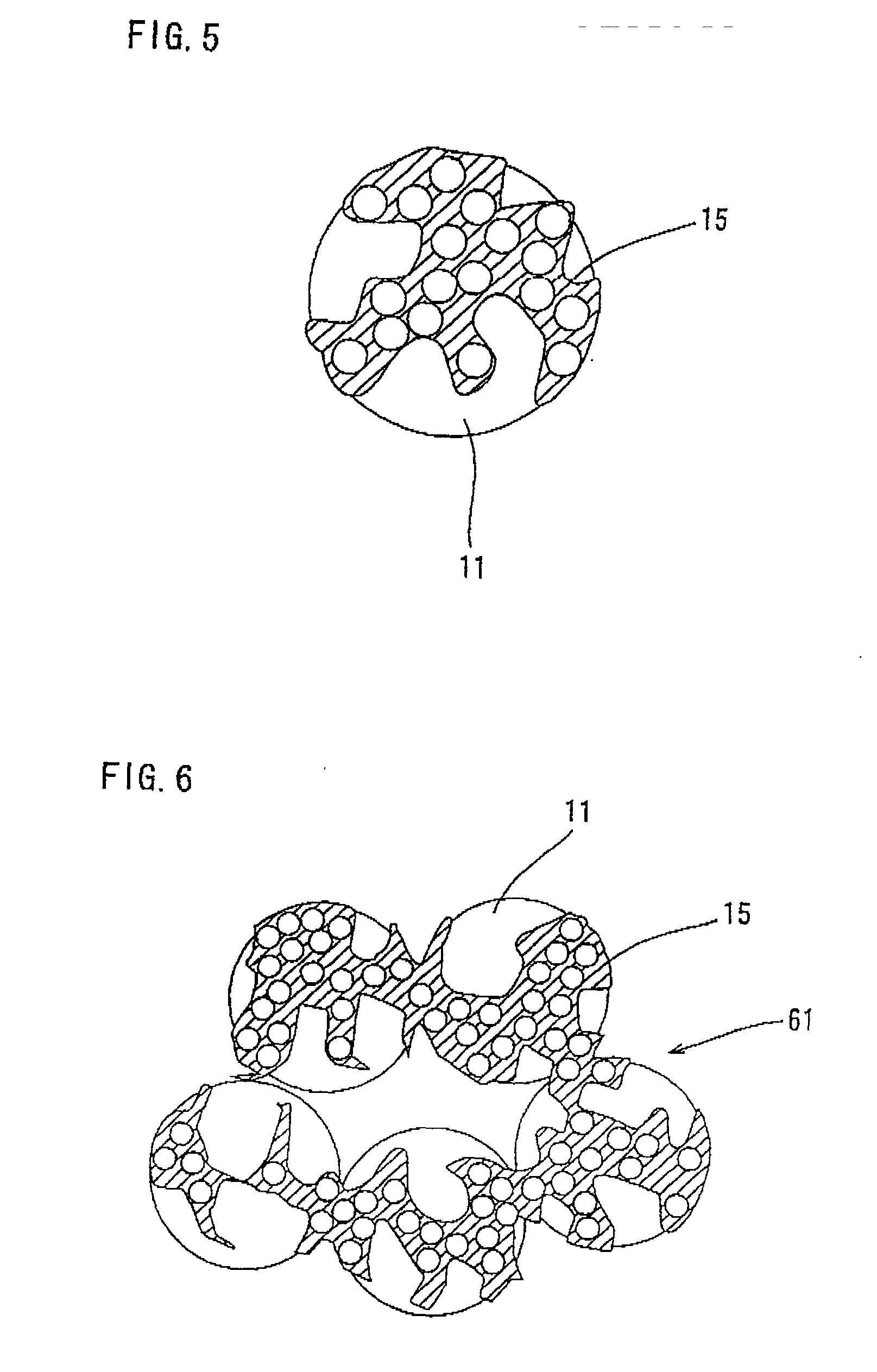
[0094] First, carbon-supporting platinum (10V30E, manufactured by Tanaka Kikinzoku K. K.; Valcan XC-72 having 30 wt % platinum supported thereon; average particle diameter of the carbon, 30 nm; average particle diameter of the platinum, 2.4 nm) was immersed at a reduced pressure of 1 Torr or lower in a PVdF-NMP solution (a) of 5 wt % PVdF. Thereafter, the excess PVdF-NMP solution (a) was removed from the mixture by suction filtration. The resultant platinum-supporting carbon particles having the PVdF-NMp solution (a) adherent thereto were immersed in water as solution (b) to extract the NMP. Thereafter, the carbon particles were subjected to suction filtration to remove water therefrom and then dried at 100.degree. C. to prepare carbon-supporting platinum whose surface was partly covered with the PVDF in a net form. Subsequently, the carbon-supporting platinum having the net-form PVdF deposited thereon were immersed in a solution (a') of a cation-exchange resin solution (5 wt % Nafi...


PUM

PropertyMeasurementUnit
Phase separationaaaaaaaaaa
Hydrophobicityaaaaaaaaaa

Abstract

A composite catalyst which comprises a catalyst particle and at least one member selected from the group consisting of a porous or net-form cation-exchange resin and a porous or net-form hydrophobic polymer, wherein the resin and polymer exist on the surface of the catalyst particle.

Description

[0001] The present invention relates to a composite catalyst suitable for use in solid polymer electrolyte type fuel cells and to processes for producing the catalyst.DESCRIPTION OF THE RELATED ART[0002] A solid polymer electrolyte type fuel cell (PEFC) is an apparatus which employs a solid ion-exchange memrane as an electrolyte and in which a fuel (e.g., hydrogen gas) and an oxidizing agent (e.g., oxygen gas) are supplied respectively to the anode and the cathode to electrochemically react these feed materials on the catalyst surfaces, thereb obtaining an electric power.[0003] For example, in the case of using hydrogen gas and oxygen gas as a fuel and an oxidizing agent, respectively, the electrochemical reactions occurring at the electrodes are as follows.Anode: H.sub.2.fwdarw.2H.sup.++2e.sup.-Cathode: 1 / 20.sub.2+2H.sup.++2e.sup.-.fwdarw.H.sub.2OOverall reaction: H.sub.2+1 / 20.sub.2.fwdarw.H.sub.2O[0004] As the formulae given above show, the reactions at the anode and cathode neces...

Claims


Application Information

Patent Timeline
IPC IPC(8): B01J21/18B01J23/42B01J31/08H01M4/88H01M4/92H01M8/10
CPCB01J21/18B01J23/42B01J31/08Y10T428/2998H01M8/1004Y02E60/522H01M4/8875H01M4/926Y02P70/50Y02E60/50
Inventor HITOMI, SHUJITSUMURA, NAOHIROMIZUTANI, SHUNSUKE
Owner GS YUASA INT LTD
Why Eureka
Try Eureka