Device and method for tuning the wavelength of the light in an external cavity laser

Inactive Publication Date: 2002-02-28
RADIANS INNOVA
View PDF0 Cites 31 Cited by
  • Summary
  • Abstract
  • Description
  • Claims
  • Application Information

AI Technical Summary

Benefits of technology

0016] When, under the influence of the electrodynamic force, the movable part moves, the second magnet will therefore also perform a movement in relation to the second coil or vice versa, as a result of which a voltage is induced in the second coil. This electromagnetic interaction between the second coil and th

Problems solved by technology

A disadvantage of using conventional motors with mechanical drives or gear devices in external cavity lasers, is that such mechanical devices prohibit simultaneous fast and accurate tuning due to the inherent friction.
One limitation in particular, results from the inherent compromise when choosing a gear ratio for either high accuracy giving low speed, or alternat

Method used


Image

  • Device and method for tuning the wavelength of the light in an external cavity laser
  • Device and method for tuning the wavelength of the light in an external cavity laser
  • Device and method for tuning the wavelength of the light in an external cavity laser

Examples


Example

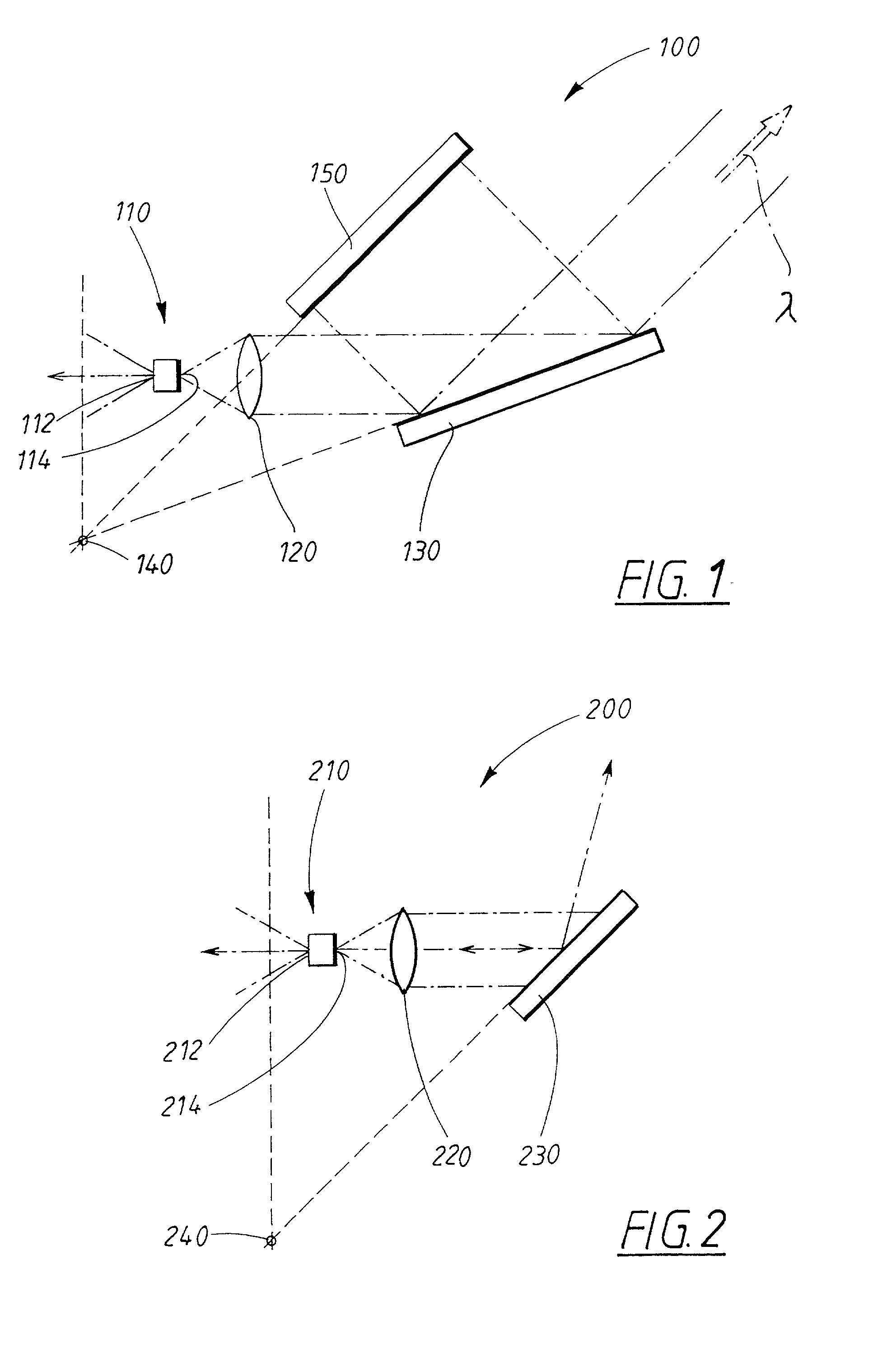
[0022] FIG. 1 shows a basic diagram of an external cavity laser (100) in which the invention can be applied. The external cavity laser (100) is constructed according to what is known as the Littman configuration, which will be explained below.

[0023] The external cavity laser (100) comprises an optically amplifying semiconductor chip (110), a first reflecting surface (112), an AR coated semiconductor chip facet (114), a diffraction grating (130), a collimating lens arrangement (120) and an auxiliary mirror (150) arranged on a movable part. The light which is emitted through the AR coated semiconductor chip facet (114) of the optically amplifying semiconductor chip (110), will be incident on the diffraction grating (130), towards which the light is collimated by means of a lens arrangement (120). From the diffraction grating (130), the light will be completely or partly diffracted towards the auxiliary mirror (150) and completely or partly reflected back towards the optically amplifyi...


PUM


Abstract

The invention relates to a device (300) for tuning the wavelength of the light in an external cavity laser. The external cavity laser comprises an optically amplifying semiconductor chip (310), a first reflecting surface (312), an Anti-Reflection (AR) coated semiconductor chip facet (314), a diffraction grating (330) on which at least part of the beam originating from the AR coated semiconductor chip facet (314) is incident and diffracted back to the optically amplifying semiconductor chip (310), means (320) for collimating the light emitted from the AR coated semiconductor chip facet (314) towards the diffraction grating (330), and a movable part (360) by means of the movement of this said part the wavelength of the light can be tuned in the external cavity laser. The movable part (360) of the external cavity laser exhibits a rotational movement relative to the optical axis of the external cavity laser, the optical axis being defined by the center of the beam propagating between the first and the second reflecting surface, said movement being actuated by an electrodynamic force generated within an integral section of said movable part.

Description

TECHNICAL FIELD[0001] The invention relates to a device and method for precise, fast and continuous tuning of a semiconductor external cavity laser, where the inherent limitations due to friction and mechanical wear are reduced to an absolute minimum.BACKGROUND ART[0002] For applications where a precise and wavelength tunable laser light source is needed, one is often required to use an external cavity stabilized semiconductor laser. A conventional laser comprises an optically amplifying medium between a first and a second reflecting surface. For a monolithic semiconductor laser these reflective surfaces are usually the end facets of the optically amplifying semiconductor chip. A fixed wavelength monolithic laser can be made tunable by providing an Anti-Reflection (AR) coating on the second semiconductor chip facet and arranging for an external movable second reflecting surface to provide wavelength selection.[0003] A plurality of methods exist for effecting wavelength selectivity, ...

Claims


Application Information

Patent Timeline
IPC IPC(8): H01S5/14
CPCH01S5/141H01S5/143
Inventor VILHELMSSON, KENNETLOCK, TOMAS
Owner RADIANS INNOVA
Why Eureka
Try Eureka