Limiter optics

a laser and optical technology, applied in the direction of laser details, excitation process/apparatus, handling using diffraction/refraction/reflection, etc., can solve the problems of limited solar panels, limited power requirements of manmade space satellites, and inability to adjust the energy received from the sun

Inactive Publication Date: 2002-04-18
BENNETT OPTICAL RES
View PDF3 Cites 5 Cited by
  • Summary
  • Abstract
  • Description
  • Claims
  • Application Information

AI Technical Summary

Problems solved by technology

Manmade space satellites are limited by their power requirements.
Solar panels are limited for two reasons.
First the energy received from the sun is relatively diffuse and is not adjustable.
For a fixed surface area the power that can be created by the solar panel is limited.
This leads to the second limitation, the mass and volume of the solar panel needed to generate the required power level.
Even the use of mirrors reduces the mass and volume available for launch payloads.
The power limitations force most satellites to be designed to operate on the power requirements of a small household appliance.
Electrical power has always been a limiting factor for satellites, and it restricts the services that they can perform.
At present the size of satellite solar panels is awkwardly large.
A major drawback of this approach is that the output signals of the various satellites are not in phase, so interference between satellite transmissions can be a problem.
The biggest drawback, however, is that the multiple satellite approach is very expensive.
In addition, the atmosphere can cause various other problems associated with turbulence, scatter, and absorption.
One problem with IFRA FEL is that the portion of the beam fed back can grow in power, increasing the output of the laser and going into a runaway situation.
A further problem with IFRA FEL is that the generated optical pulse is of the same duration as the electron bunch that emitted the pulse.
This causes phasing problems unless the optical feedback loop can be accurately controlled.
Any portion of an electron bunch out of phase with the optical pulse is wasted.

Method used


Image

  • Limiter optics
  • Limiter optics
  • Limiter optics

Examples


Embodiment Construction

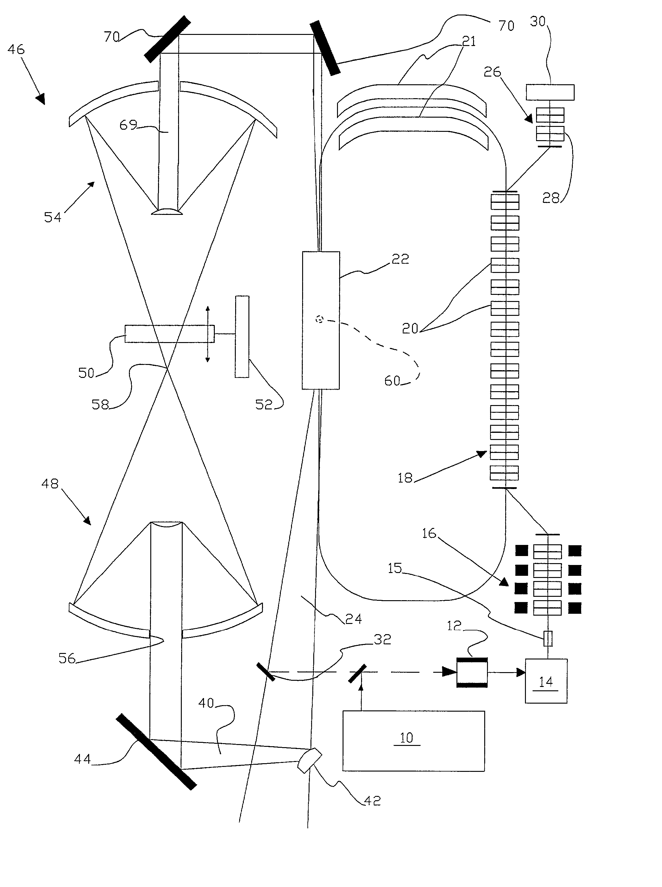
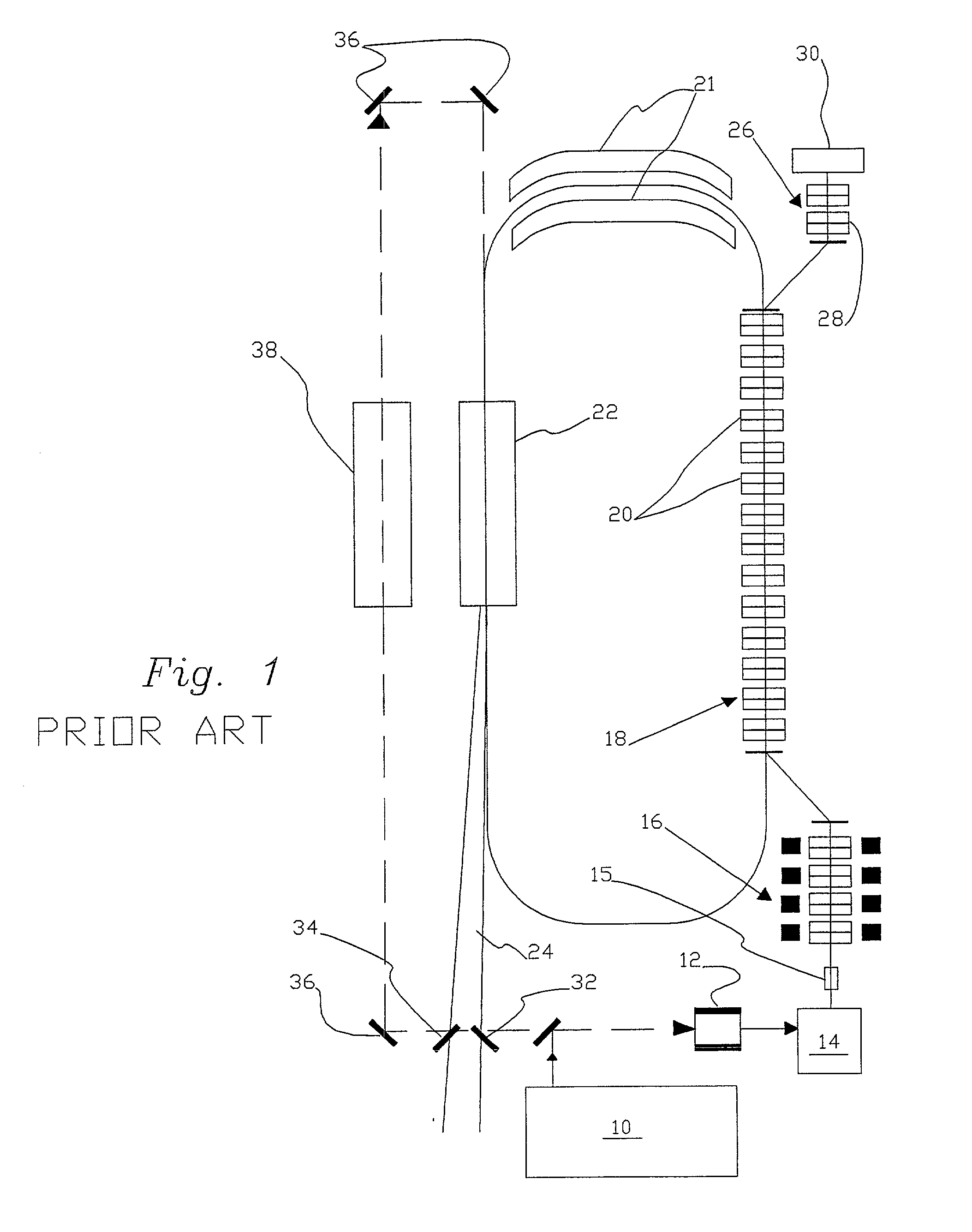
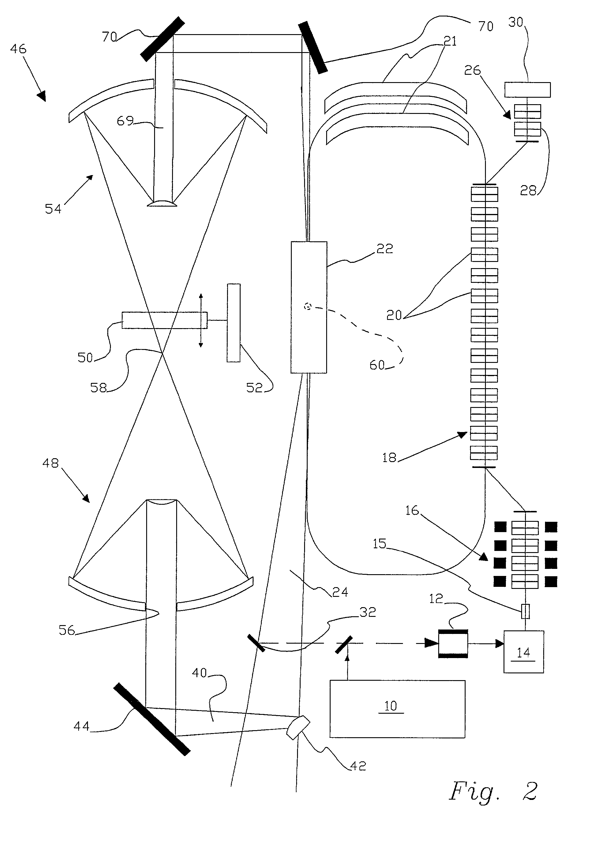
[0021] FIG. 1 is an example of a typical ignition feedback regenerative free electron laser (FEL) amplifier, IFRA FEL, suitable for laser power beaming, LPB. An optical pulse laser 10 has an up-converter 12 take an initial ignition pulse and convert it to a suitable wavelength before it is used to illuminate photocathode 14. Up-converter 12 will not change quality or intensity of light passing through it, but does convert to the best frequency for emission of photons with a given quality and intensity. Photocathode 14 in turn emits a bunch of electrons 15 with a pulse width determined by the design parameters of laser 10 and photocathode 14. This electron bunch is immediately accelerated by an initial accelerator 16. The electron bunch is now directed through a linear accelerator 18, which may have a large number of cooled RF cavities 20 operating near room temperature. Electron bunch 15 is now accelerated by the RF cavities to a speed very close to the speed of light. Electron bunc...


PUM


Abstract

Limiter optics for an ignition feedback regenerative free electron laser amplifier have a pickoff mirror direct a portion of the output from the free electron laser through a focusing assembler. After expanding this pickoff beam spatially and temporally, the focusing assembler first focuses the expanded pickoff beam to a focal point, the expanded focused pickoff beam is then passed through a movable limiter plate which serves as an off switch if the pickoff beam is above a predetermined intensity and then refocuses the expanded pickoff beam back into the free electron laser to enhance the emission intensity of the output beam. The expanded mirror may be a half silvered mirror or a phased mirror with a plurality of mesas. The pickoff mirror may be convex. The half silvered mirror produces two segments in the pickoff beam with a time lag dependent on the thickness of the mirror. The phased mirror creates a plurality of parallel beams for the expander beam with a predetermined time lag for each of said paralleled beams created. Orientation of a phased mirror may be rotated to control spatial separation of parallel beams.

Description

[0001] This is a continuation-in-part of Ser. No. 60 / 178,531, filed Jan. 25, 2000.[0002] 1. Field of the Invention[0003] The invention relates in general to the control of high-powered lasers, and, in particular, to improving the reliability, safety and power output of free electron lasers.[0004] 2. Description of the Prior Art[0005] Manmade space satellites are limited by their power requirements. Solar panels have long been used to provide power for satellites. Solar panels are limited for two reasons. First the energy received from the sun is relatively diffuse and is not adjustable. For a fixed surface area the power that can be created by the solar panel is limited. The greater the power, the larger the surface area required. Mirrors have been used in space to reflect more sunlight on a fixed area. This leads to the second limitation, the mass and volume of the solar panel needed to generate the required power level. For high power levels the mass and volume can force reduction...

Claims


Application Information

Patent Timeline
Patent Type & Authority Applications(United States)
IPC IPC(8): G21K1/06H01S3/00H01S3/09
CPCG21K1/06H01S3/0903H01S3/005
Inventor BENNETT, HAROLD E.
Owner BENNETT OPTICAL RES
Why Eureka
Try Eureka