
Co-probe power generation system

a power generation system and co-probe technology, applied in the direction of electric generator control, renewable energy generation, greenhouse gas reduction, etc., can solve the problems of all conventional fossil-burning utilities, pollution of the earth's atmosphere, damage to the protective ozone layer of the planet at high altitude,

Inactive Publication Date: 2002-05-02
CADDELL ROBERT I +1
View PDF0 Cites 29 Cited by
  • Summary
  • Abstract
  • Description
  • Claims
  • Application Information

AI Technical Summary

Benefits of technology

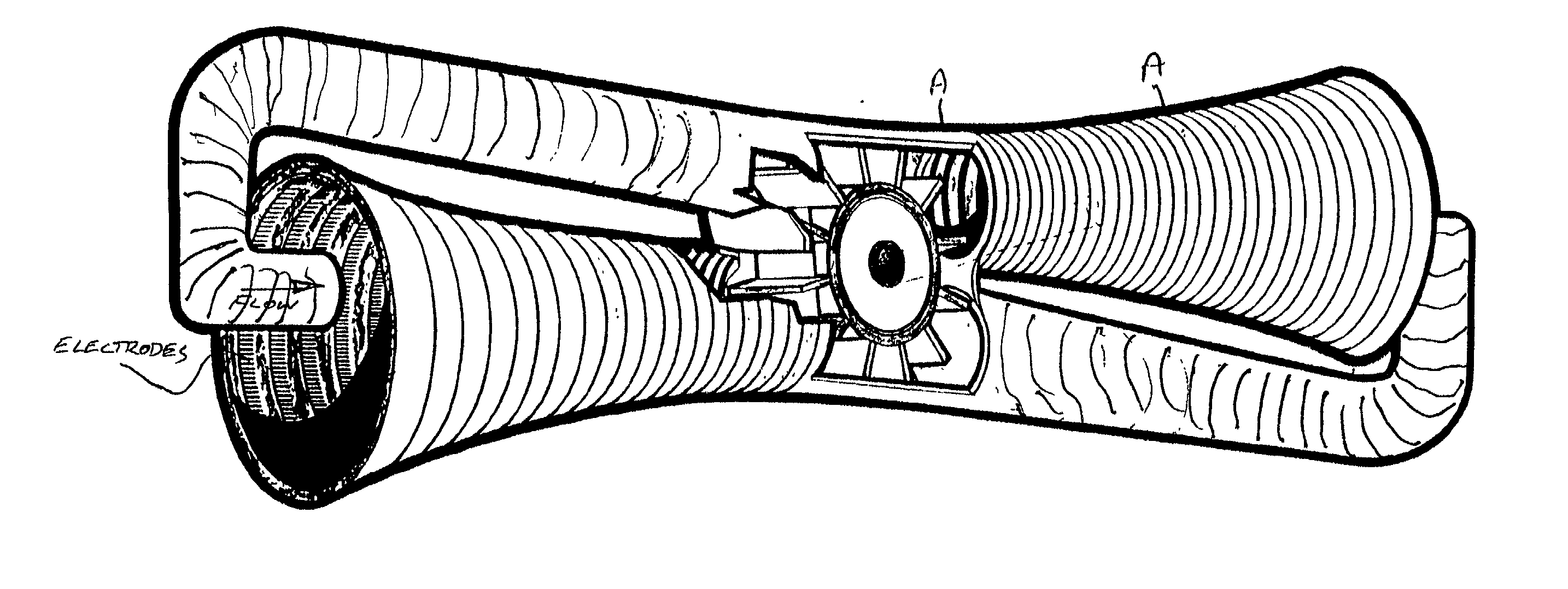
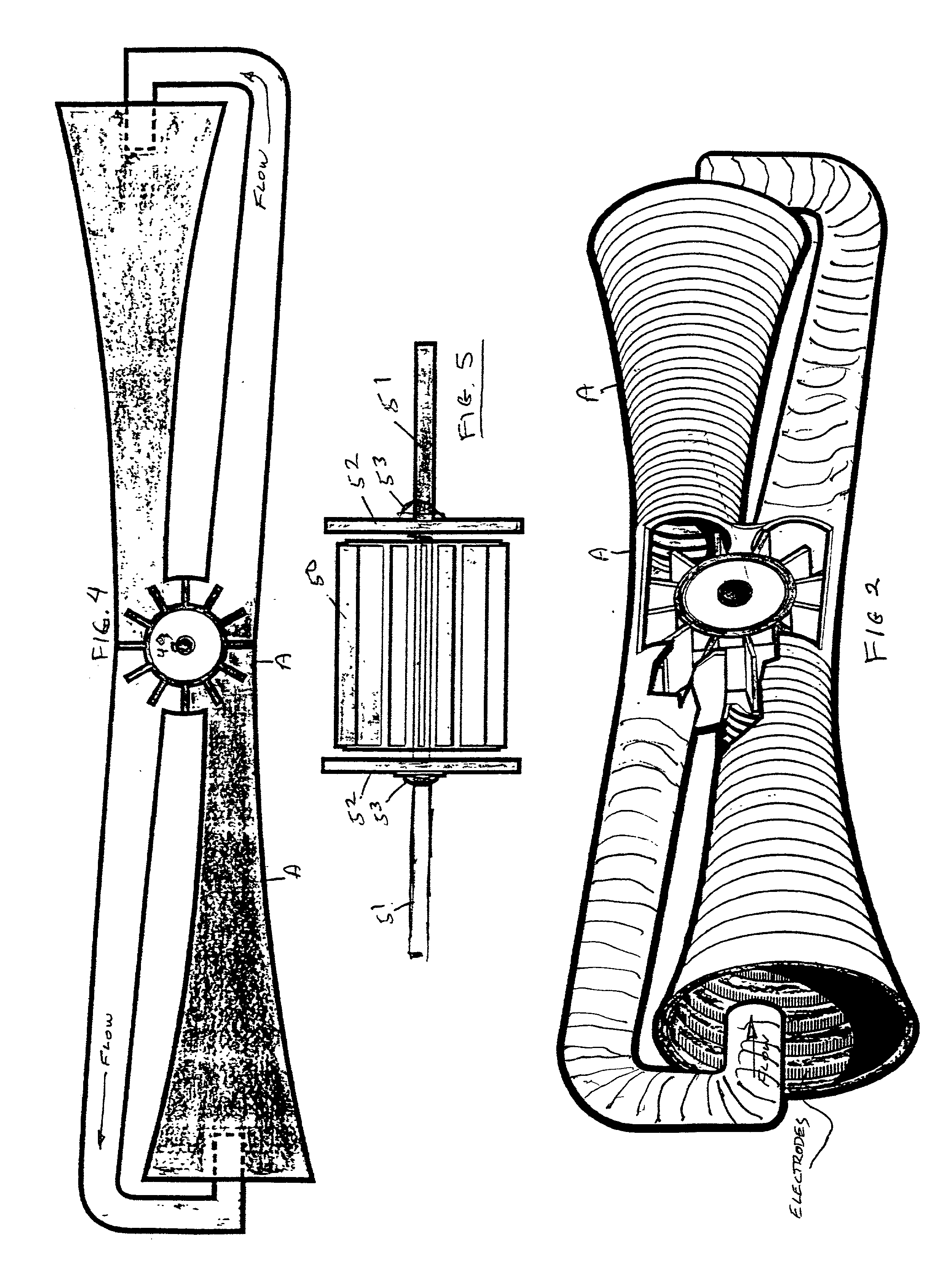
[0019] The concavely curved surface of the wind generator's inner walls may be employed to minimize the capture and loss of charged particles by the electrodes; this is accomplished by orienting the electrodes to drive the ions or charged particles around the curved walls thereby producing centrifugal forces which motivate the ions or particles away from the curved surface. These centrifugal forces are generally in the same direction as, and supplement, the working pressure produced in the throat of the fluid-force generator tunnel.
[0020] As previously stated, the preferred excitation systems employ periodically changing potentials, and these systems are designated herein as alternating potential systems. At resonance each pulse of ions will flow across or pass the electrode attracting them when that electrode changes polarity, and the charged particles are further accelerated in the same flow direction by repulsion from this electrode and attraction toward the next electrode which is now of opposite polarity. If the accelerating voltage gradient between the electrodes and the frequency are properly adjusted, these pulses of ions will flow from one electrode to the next in synchronism or resonance with respect to the changing electrode potentials. This resonance may be obtained by adjusting either the accelerating voltage gradient or the frequency. When resonance is achieved, a minimum number of ions or charged particles will be captured by the electrodes thereby minimizing the current loss and increasing the efficiency of operation. This current loss may be further decreased by decreasing the width of the ion pulse so that more of the ions can cross the electrode while there is essentially no electric field between electrodes. The effectiveness of the alternating potential excitation including the minimizing of current losses may be controlled by the selection of the wave form of the alternating potential and also by various designs of the configuration and dimensions of the electrodes.
[0026] It is another object of this invention to provide an improved and reliable method to generate electricity without the burning of fossil fuels or any other type of fuel.
[0028] It is another object of this invention to provide an improved method of creating fluid forces capable of efficiently turning turbine blades at their maximum rated speeds.
[0029] It is another object of this invention to provide an improved system for maintaining a flow of fluids through wind tunnels, ducts and the like with a minimum of turbulence.

Problems solved by technology

Carbon-fuel-burning utilities are polluting the earth's atmosphere and causing damage to the planet's high-altitude protective ozone layer.
All conventional fossil-burning utilities have the common-costly problems associated with long-distance-alternating-current (AC) power transmission.
These problems include: corona discharge which, unless the transmission line has an expensive large diameter conductor can leak up to forty percent of the transmitted energy; storm induced transmission line downtime; lightning strikes; and losses that are attributed to power-line resistance and inductance.
Whereas High-Voltage-Direct-Current (HVDC) transmission lines have less line losses than HVAC, they have many undesirable and limiting features.

Method used


Image

  • Co-probe power generation system
  • Co-probe power generation system
  • Co-probe power generation system

Examples


Embodiment Construction

[0054] While the invention will be described and disclosed here in connection with certain preferred embodiments, the description is not intended to limit the invention to the specific embodiments shown and described here, but rather the invention is intended to cover all alternative embodiments and modifications that fall within the spirit and scope of the invention as defined by the claims included herein as well as any equivalents of the disclosed and claimed invention.

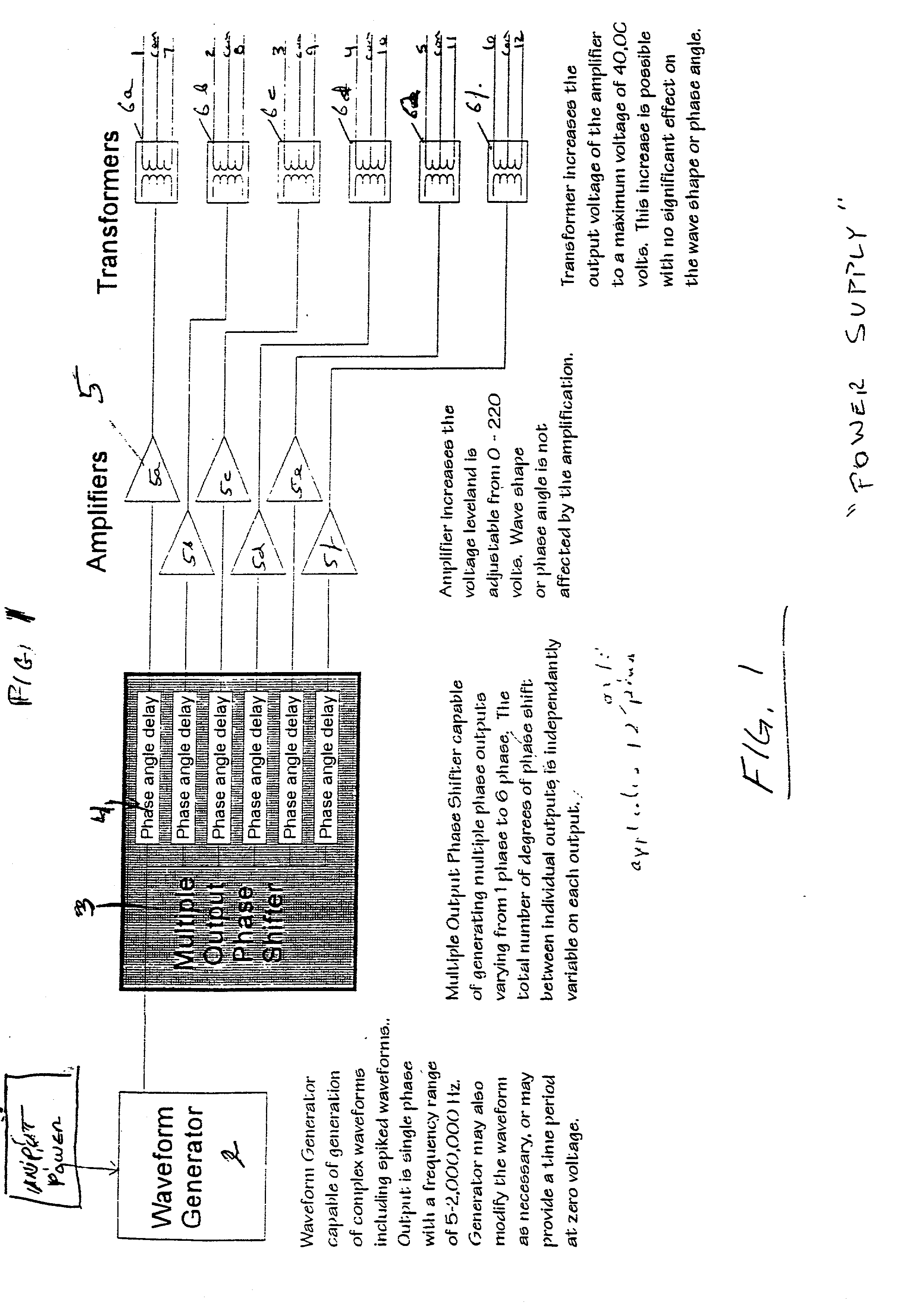
[0055] Turning now to FIG. 1 where a block diagram of a new and unique power supply system for use with this invention has been shown. The invention described herein employs a power supply having an alternating potential with periodically changing and timed electric potentials having specified waveforms, a multiple output phase shifter, voltage amplifiers and transformers to further increase the power supply's output voltage. The block diagram illustrated in FIG. 1 is an example of this invention's power supply sys...


PUM


Abstract

A fluid moving system that includes a multiplicity of electrode elements mounted in spaced relationships to one another adjacent along a surface. The electrode elements produce charged particles by a corona-type discharge. The electrode elements are also used for delivering progressively changing electric potentials along the smooth surface in order to create an electric potential field for propelling charged particles from one electrode element toward the next and thereby inducing a surface layer fluid flow over the surface. A switching mechanism for reversing the direction of the corona discharge and the direction of the moving charged particles is also incorporated into the system in order to reinforce and accelerate the flow.

Description

REFERENCE TO RELATED APPLICATIONS[0001] This application claims the benefit of my provisional application having Ser. No. 60 / 211,102, filed Jun. 12, 2000, now abandoned.[0002] (a) Field of the Invention[0003] This invention generally relates to a system and method for accelerating fluids. More particularly, but not by way of limitation, to a system for generating power from fluids accelerated by way of an electrical potential difference.[0004] (b) Discussion of Known Art[0005] In a letter to the editor of the publication The Review of Scientific Instruments April, 1954, "Ionic Pump" by A. M. Gurewitsch and W. F. Westendorf of the General Electric Research Laboratory, an ionic pump that depends upon the production of ions by electrons oscillating in a combined electric and magnetic field is discussed. According to this article in an ionic pump ions are accelerated by an electric field and are driven into absorbing surfaces represented by carbon disc or other absorbing materials. In U...

Claims


Application Information

Patent Timeline
IPC IPC(8): F02K7/12F03D3/00F03H1/00
CPCF02K7/12F03D3/002F03H1/00Y02T50/671F05B2240/216Y02E10/74F05B2210/16Y02T50/60
Inventor CADDELL, ROBERT I.PROSSER, PAUL L.
Owner CADDELL ROBERT I
Learn More