[0010] According to one embodiment of the present invention an amplifier characterized by gain and output power comprises: (i) at least one gain medium; (ii) a pump supplying
optical power into said gain medium; (iii) a controller controlling said gain and said output power of said amplifier. This controller includes an electronic gain switch to cover a
wide dynamic range for optical input and output signals, so that resolution for low optical signals is better than resolution for high optical signals.
[0028] The driver circuits 145 may include, for example, a logarithmic amplification (compression) circuit 195A (not shown). The Logarithmic amplification (compression) circuit 195A performs a logarithmic calculation (such as log10, for example) of electrical input or output signals, corresponding to input and output optical powers, with analog
electronics. In this way, the wide range of input or output optical powers is compressed and can be represented by a limited number of bits of A / D converter. This compressed electrical signal provided by the logarithmic amplification circuit is sampled and converted to the digital domain. At this point, this
digital signal can be processed directly, or decompressed by performing an anti-log function with the digital-
processing algorithm. Furthermore, when the electrical signal (corresponding to
optical power) is transformed by a logarithmic function, input or output signals corresponding to low optical power can be represented by a larger number of bits, improving the resolution of these signals and therefore, improving the accuracy of gain / output
power control.
Dynamic Range Switching
[0029] The other option for increasing
dynamic range performance involves
direct control of the value of the analog input signal that enters the A / D converter. To increase the resolution of the conversion the A / D converter needs to see a higher
analog signal (higher
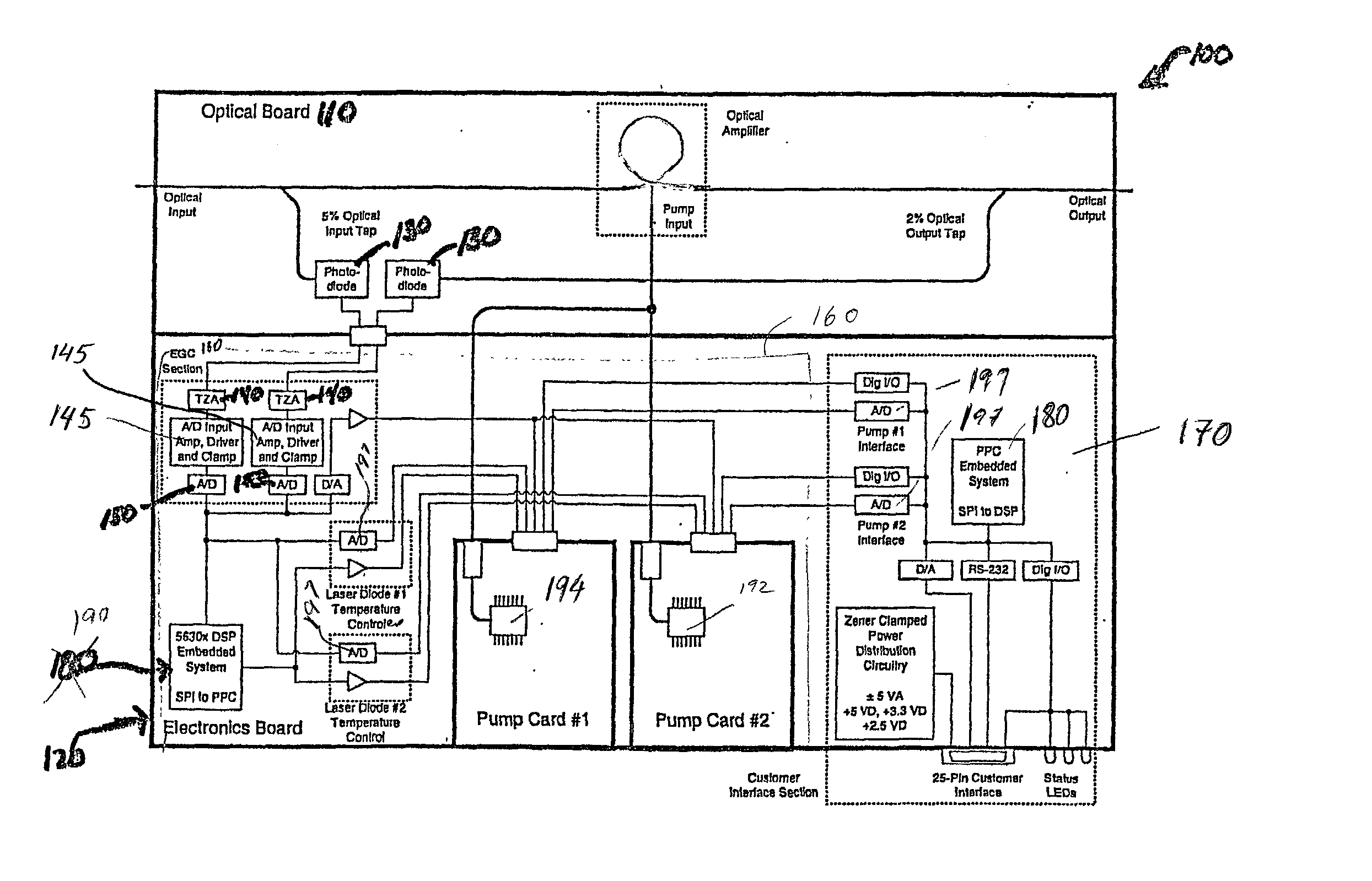
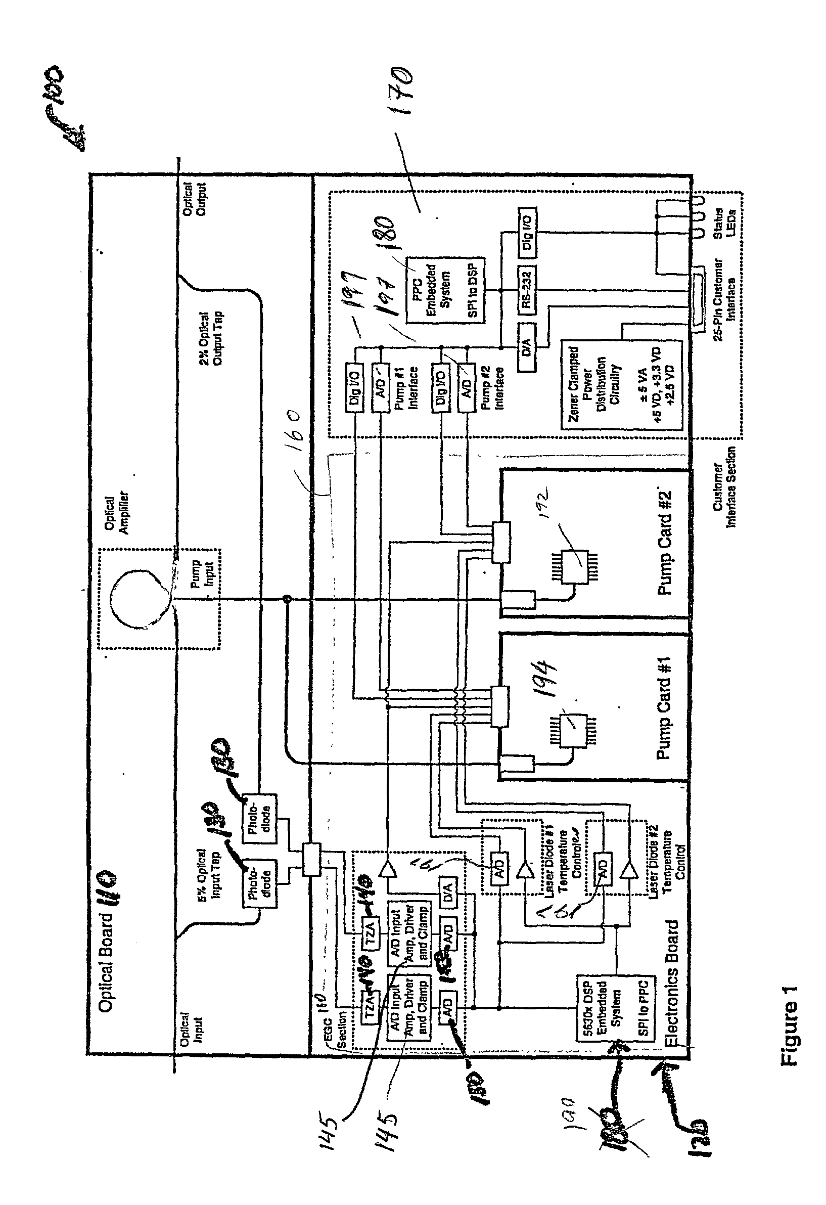
voltage) representing optical signal power when optical input signal is small. Thus, section 160 includes A / D converter, a TZA (trans-impedance amplifier) that converts
electrical current values, provided to it by a photo-
detector, to
voltage, and also includes A / D drivers which convert
voltage provided by a TZA (trans-impedance amplifier) to a different
voltage range suitable as input to the A / D converter. When this approach is utilized, the A / D
driver circuit 145 includes a gain switch 195B. When the optical input signal is small (for example, less than -25
dBm), this gain switch 195B multiplies (for example by a factor of 16) and thus increases the
analog signal provided to the A / D converter, which will increase resolution (conversion accuracy) for the
low input signals. Thus, in normal operating mode, when the optical signals are low or not very large, the gain switch of A / D drivers would be set to its maximum value, allowing for the best signal-to-
noise ratio.
[0030] If either of the input signals to the drivers 145 (i.e., the signals corresponding to the optical input and output powers, respectively) becomes very large, an overflow condition will result. The digital value sampled by the AGC section 160 will be at it's maximum, and will not represent the actual value corresponding to the power of the optical signal. The AGC section 160 automatically recognizes that the input signal is in an overflow condition (i.e. the input value being at maximum for a pre-defined, minimum period of time). At this point, the electronic gain of the saturated A / D driver can be reduced with the proper synchronization with the digital
processing algorithm. With this gain reduced, the analog input signal to the A / D converter would no longer be in an overflow condition and
normal control processing continues. It is preferable that a
hysteresis is used to avoid unnecessary, oscillatory
gain switching, caused by
noise. This
noise may be introduced by fluctuations in the optical signal power or can be introduced by electronic circuits.
[0031] Another novel feature of this amplifier involves the usage of fast electronic A / D
converters 197 designed for use in a different industry (in this case, the audio industry). The multiple A / D
converters 197 are pre-packaged in a
single chip, take very little space and are more reliable than if multiple separate A / D chips are used. Therefore, by utilizing a
single chip A / D
converters 197 we achieve reduced cost and maximum
product lifetime. These
single chip A / D converters 197 enable simultaneous sampling of electrical signals representing temperature of the pump lasers. This simultaneous sampling allows the AGC section 160 to control the
laser diode temperature with minimal processing time. Once the signals representing the input and output optical powers and temperature of the pump lasers are sampled, the digital nature of the AGC section 160 allows easy implementation of different control
modes. For example, this controller 120 utilizes two
alternative control modes: (i) optical output
power control and (ii) optical gain
control mode. The control
modes are selected by the operator, via remote commands, for example. Only one
control mode is used at the time and the switch from one mode to another mode is be made by operator's command.

