

Illuminating devices and window glasses employing titanium dioxide photocatalysts
- Summary
- Abstract
- Description
- Claims
- Application Information
AI Technical Summary
Benefits of technology
Problems solved by technology
Method used
Image

Examples
example 1
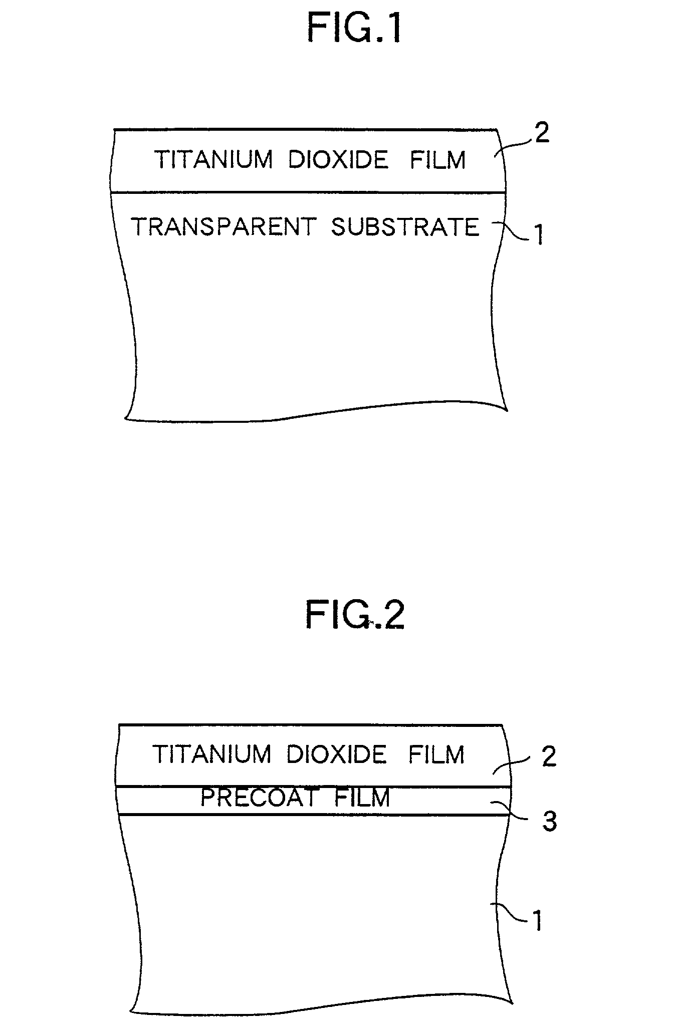
[0063] FIG. 1 is a partially sectional diagram for illustrating the configuration of a titanium dioxide photocatalyst structure according to Example 1 of the photocatalyst structure of the present invention. Hereinafter, Example 1 of the titanium dioxide photocatalyst structure and a method for producing this titanium dioxide photocatalyst structure will be described with reference to FIG. 1.
[0064] As shown in FIG. 1, in the case of this example of the titanium dioxide photocatalyst structure, a titanium dioxide film 2 is formed on a transparent substrate 1.
[0065] The transparent substrate 1 is a soda lime glass substrate whose thickness, longitudinal size and lateral size are 1, 100 and 50 mm, respectively.
[0066] The film 2 is a titanium dioxide film which contains anatase crystals and is 4.8 .mu.m in thickness.
[0067] The aforementioned titanium dioxide photocatalyst structure was produced by performing the following process.
[0068] First, a transparent substrate 1 was produced by e...
example 2 to example 6
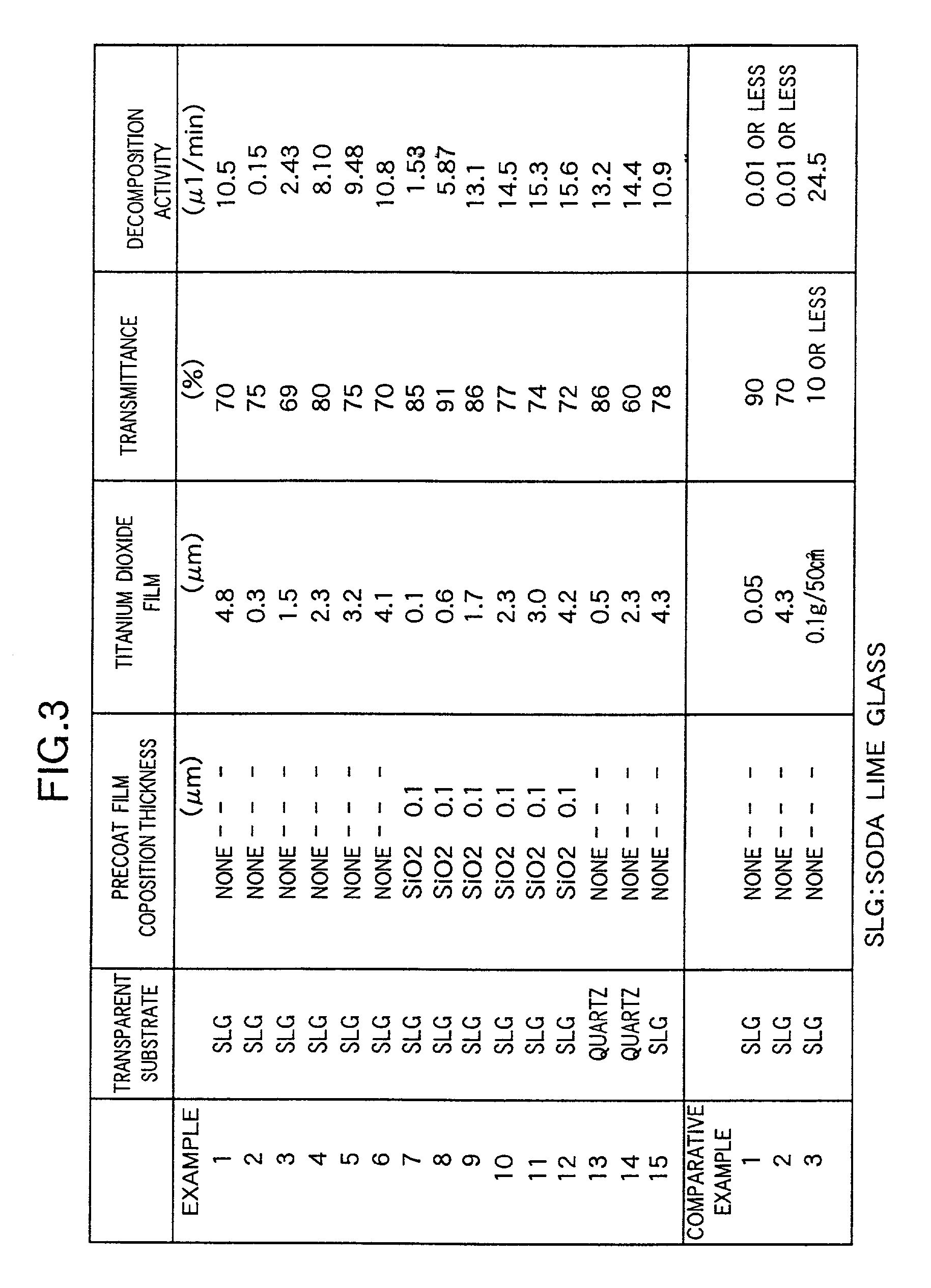
[0078] These Examples have structures, which are similar to the structure of Example 1 except that the thickness of the titanium dioxide film 2 is different from that of the film 2 of Example 1, and are produced by a producing method similar to that employed in the case of Example 1. Data representing the thickness of each Example and results of measurement of the photocatalytic activity and light transmittance are shown in FIG. 3 in tabular form. Further, the detailed description of the data is omitted.
[0079] As is seen from the table of FIG. 3, each of these Examples has excellent photocatalytic activity and sufficient transparency.
example 7 to example 12
[0080] These Examples have structures, which are similar to the structure of Example 1 except that a precoat film 3 constituted by a SiO.sub.2 film is formed between the titanium dioxide film 2 and the transparent substrate 1 by a dip coating as illustrated in FIG. 2, and are produced by a producing method similar to that employed in the case of Example 1. Data representing the thickness of each Example and results of measurement of the photocatalytic activity and light transmittance are shown in FIG. 3 in tabular form. Further, the detailed description of the data is omitted.
[0081] As is seen from the table of FIG. 3, even when the thickness of the titanium dioxide film 2 is reduced, excellent photocatalytic activities are exhibited, in comparison with Example 1 to Example 6 which do not have the precoat film 3. Thus, further higher transparency can be ensured.
PUM
| Property | Measurement | Unit |
|---|---|---|
| Fraction | aaaaa | aaaaa |
| Fraction | aaaaa | aaaaa |
| Mass | aaaaa | aaaaa |
Abstract
Description
Claims
Application Information