Large diffraction grating for gas discharge laser

Inactive Publication Date: 2002-09-12
CYMER INC
View PDF41 Cites 66 Cited by
  • Summary
  • Abstract
  • Description
  • Claims
  • Application Information

AI Technical Summary

Benefits of technology

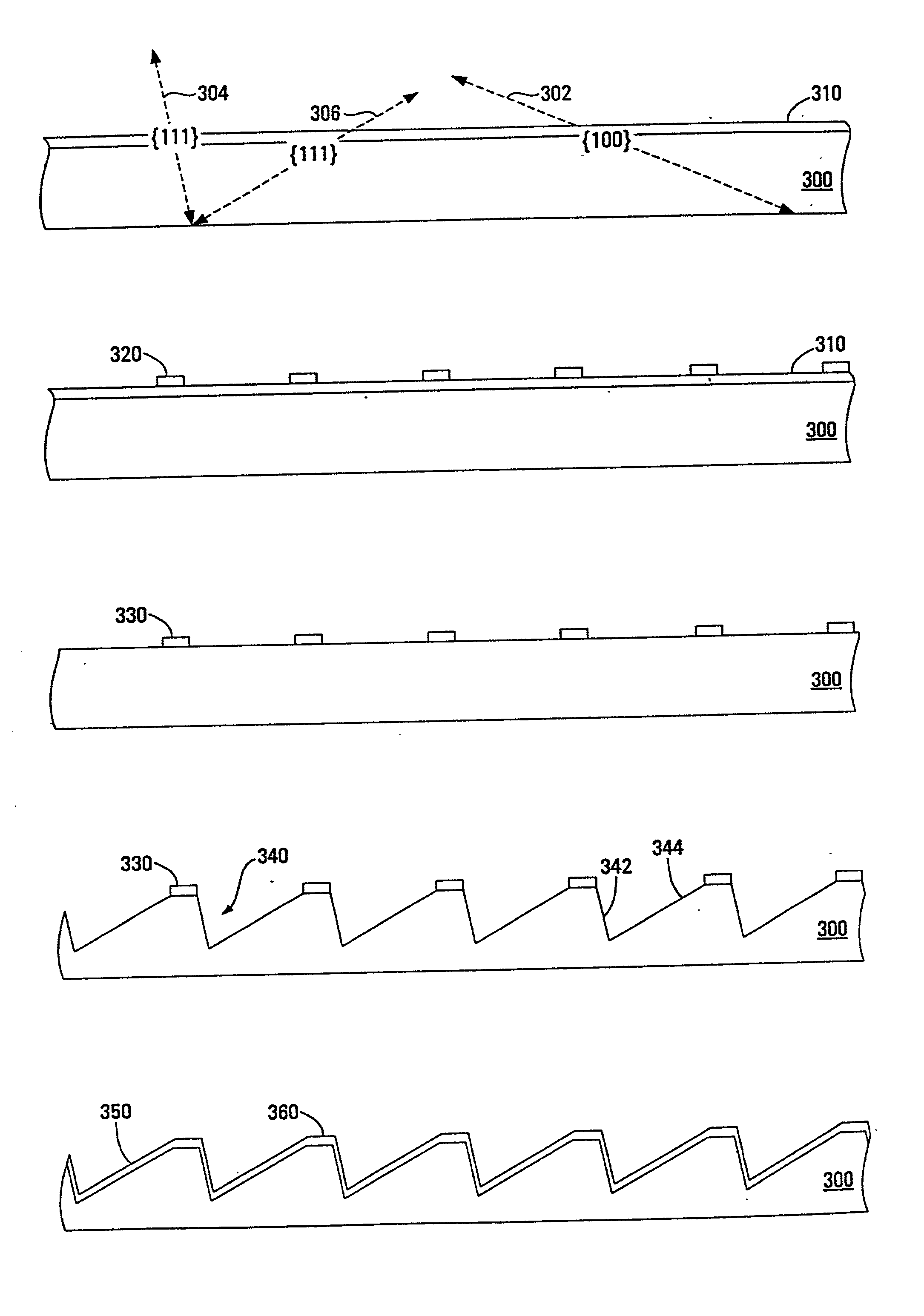
0012] The present invention provides for a grating based line narrowing unit for gas discharge lasers with increased beam expansion to produce smaller bandwidths. The grating has a grating surface larger than 100 cm.sup.2 and is a replica grating produced from a master grating produced with a lithography process on a single crystal substrate. In preferred embodiments, a beam from the chamber of the laser

Problems solved by technology

However, there are a number of difficulties associated with ruling gratings.
Echelles are considered to be among the most difficult gratings to rule because high diffraction angles require exceptional ruling accuracy, yet this must be accomplished under high tool loads that usually accompany coarse groove spacing.
Ruling engines used to fabricate echelles in this manner are complex mechanical devices that are slow and difficult to use, leading to gratings th

Method used


Image

  • Large diffraction grating for gas discharge laser
  • Large diffraction grating for gas discharge laser
  • Large diffraction grating for gas discharge laser

Examples


Embodiment Construction

[0022] Preferred embodiments of the present invention can be described by reference to the drawings.

Two Direction Beam Expansion

[0023] In reality, formula (1) presented in the Background Section only works when all the beams incident on the grating have the same direction in the vertical axes, and this direction is normal to diffraction grating grooves. Diffraction grating grooves are placed vertically so formula (1) works for beams which lay in the horizontal plane.

[0024] Real excimer laser beams, however, have some divergence in both horizontal and vertical directions. In this case, formula (1) is modified and becomes

2dn sin .alpha..multidot.cos .beta.=m.lambda. (2)

[0025] In this formula, .beta. is the beam angle in the vertical direction, the rest of the variables are the same as in (1). In the case of .beta.=0; i.e., when the beam has no divergence in the vertical direction, cos .beta.=1 and formula (2) becomes (1).

[0026] It is important to note, that the grating does not have a...


PUM


Abstract

A grating based line narrowing unit for gas discharge lasers with increased beam expansion to produce smaller bandwidths. The grating has a grating surface larger than 100 cm.sup.2 and is a replica grating produced from a master grating produced with a lithography process on a single crystal substrate. In preferred embodiments, a beam from the chamber of the laser is expanded with four prism beam expanders. The large grating, much larger than gratings historically produced from diamond lined gratings, permit substantial reductions in bandwidth while maintaining laser efficiency. A narrow band of wavelengths in the expanded beam is reflected from a grating in a Littrow configuration back via the bi-directional beam expanders into the laser chamber for amplification.

Description

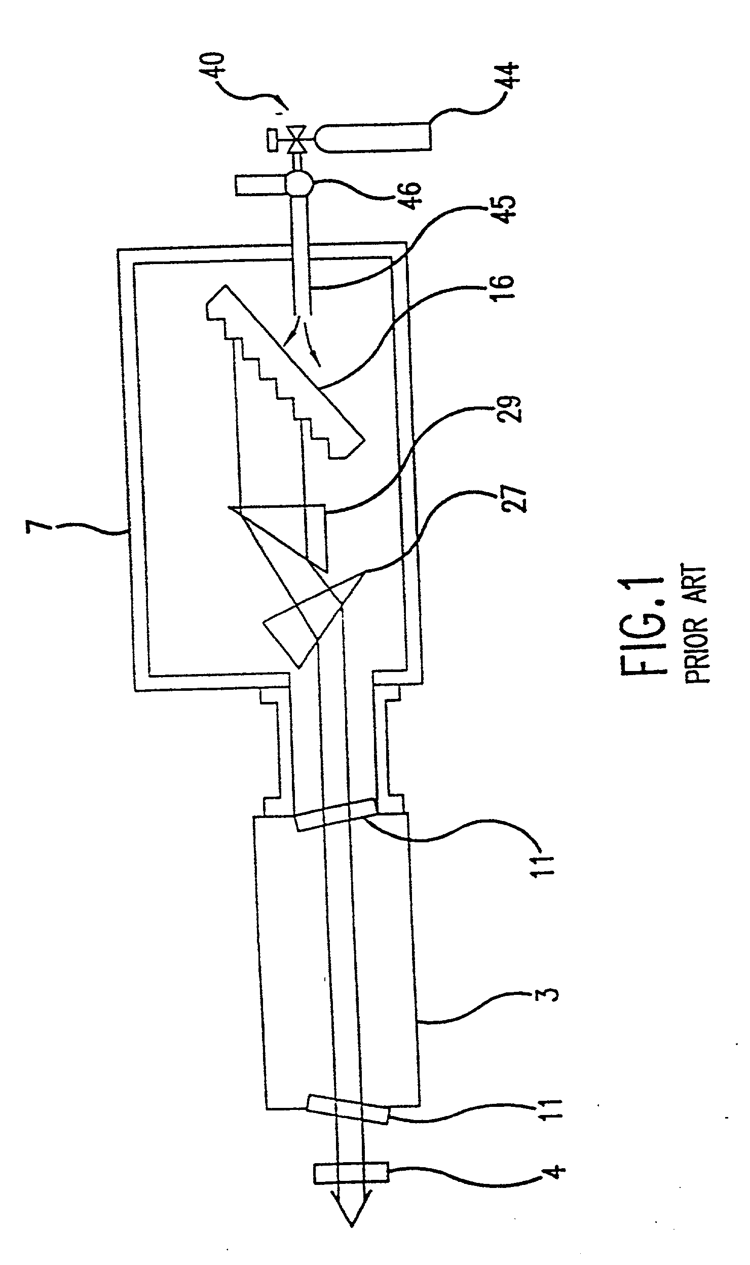
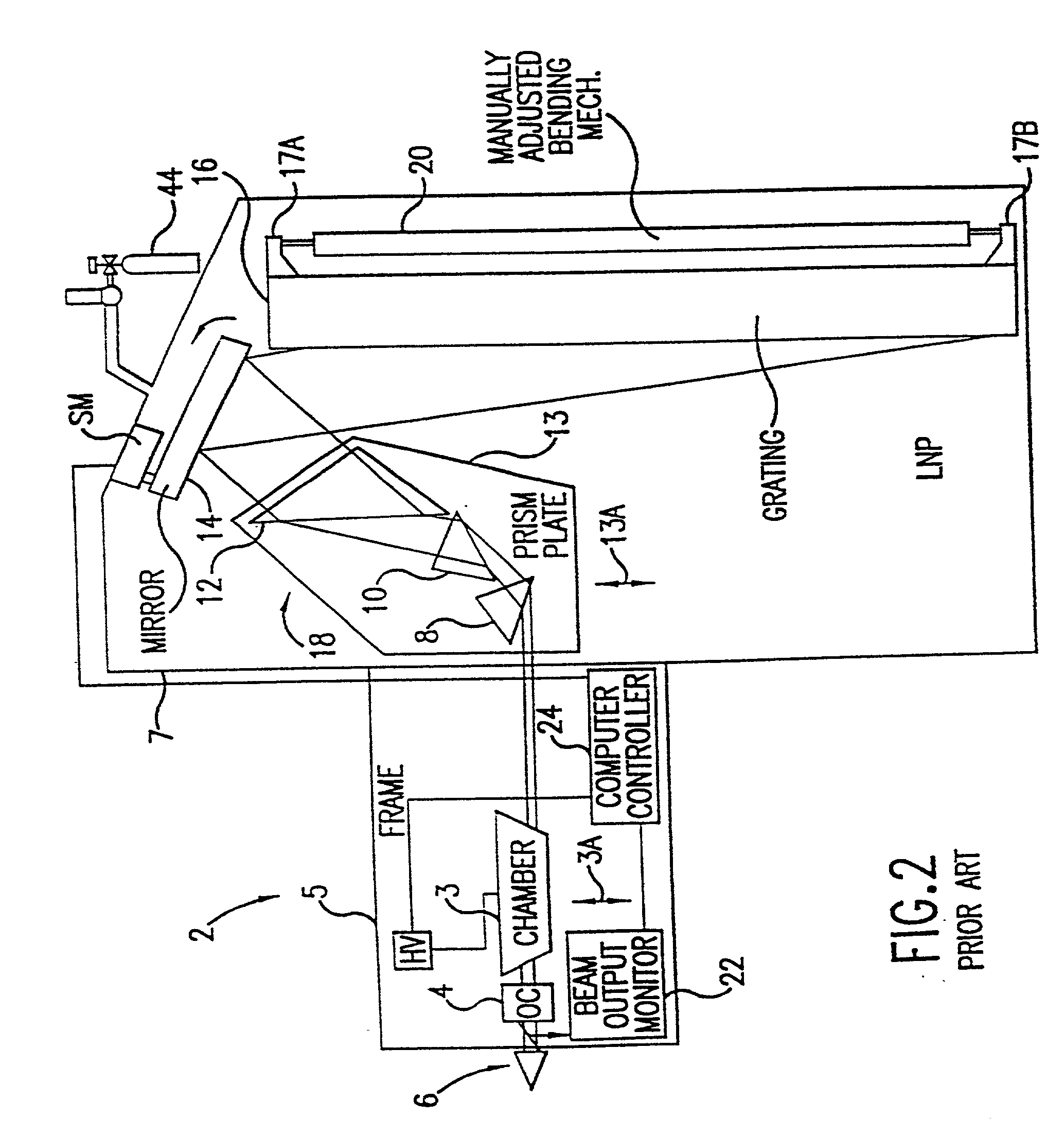
[0001] This invention relates to lasers and in particular to line narrowed excimer lasers. This invention is a continuation-in-part of Ser. No. 09 / 151,128, filed Sep. 10, 1998; Ser. No. 09 / 470,724, filed Dec. 22, 1999; Ser. No. 09 / 703,317, filed Oct. 31, 2000; Ser. No. 09 / 716,041, filed Nov. 17, 2000 and Ser. No. 09 / 943,343, filed Aug. 29, 2001.BACKGROUND OF THE INVENTIONNarrow Band Gas Discharge Lasers[0002] Gas discharge ultraviolet lasers used as light sources for integrated circuit lithography typically are line narrowed. A preferred line narrowing prior art technique is to use a diffraction grating based line narrowing unit along with an output coupler to form the laser resonant cavity. The gain medium within this cavity is produced by electrical discharges into a circulating laser gas such as krypton, fluorine and neon (for a KrF laser); argon, fluorine and neon (for an ArF laser); or fluorine and helium and / or neon (for an F.sub.2 laser).Prior Art Line-Narrowing Technique[000...

Claims


Application Information

Patent Timeline
IPC IPC(8): G02B5/18
CPCG02B1/02G02B5/1857G02B5/1861
Inventor BROWN, DANIEL J. W.ERSHOV, ALEXANDER I.SMITH, SCOTT T.OZARSKI, ROBERT G.
Owner CYMER INC
Why Eureka
Try Eureka