
Apparatus and methods for high resolution separation and analysis of compounds

a high-resolution, compound technology, applied in the field of microdispensing apparatus for sampling, can solve the problems of not keeping up with analysis technology, present sampling technology has limited use in many of these situations, and the approach of matrix assisted laser desorption ionization (maldi) does not work

Inactive Publication Date: 2002-09-26
PROTEOME SYST LTD
View PDF6 Cites 8 Cited by
  • Summary
  • Abstract
  • Description
  • Claims
  • Application Information

AI Technical Summary

Benefits of technology

[0019] The advantage of the apparatus according to the first aspect of the present invention is that very small samples with minute amounts of compounds can be sampled accurately. The compounds that are retained by the apparatus can be eluted in concentrated form in small accurate volumes for further analysis. Relatively large volumes of sample (in the .mu.L range)(can be passed through the jetting tube and the compound(s) of interest will be captured by the collecting means. Depending on the collecting means used, the retained compound(s) can be released by change of conditions of the liquid passing the jetting tube. The eluting conditions include, but not limited to, ionic strength, solvent, salts, surfactants, chemical stripping, pressure drop or increase and the like.
[0040] Increasingly, there has been a need to generate a "sequence tag", which is a short stretch of sequence generated by either mass spectrometry-derived fragmentation or enzymatic degradation of a peptide, to facilitate the identity of the protein or to study post-translational modification on the peptide of interest. However, generating fragment data in a MALDI is not trivial. There are two approaches: the first is an experiment called post-source decay, which effectively tunes the mass spectrometer detector to detect metastable fragments induced by the laser desorption. The second is enzymatic (protease) degradation in situ on the target biomolecule, which generates a peptide ladder; the mass difference between fragments results from the enzymatic release of amino acids. Both approaches would be simplified if the peptide fragments were arrayed in a manner that facilitated their separation from contaminating peptides. In addition, the capacity to array peptides would also enhance the protein coverage, as the problem of ion suppression is addressed by the process of separating the peptide mixture into simpler components in a time dependent and, hence, spatial manner.

Problems solved by technology

Unfortunately, the development of systems to handle very small volumes of compounds in extremely low concentrations has not kept up with the analysis technology.
Present sampling technologies have limited use in many of these situations.
This approach does not work for matrix assisted laser desorption ionization (MALDI), however, as there is no liquid interface.
While it is not necessary to separate the peptide prior to implementing the PSD experiment (candidate peptides are chosen by ion-selection), the process is neither automated nor robust.
Many candidate peptides are suppressed by neighboring ions and hence are not sufficiently ionized for selection.

Method used


Image

  • Apparatus and methods for high resolution separation and analysis of compounds
  • Apparatus and methods for high resolution separation and analysis of compounds
  • Apparatus and methods for high resolution separation and analysis of compounds

Examples


Embodiment Construction

Microdispensing Apparatus

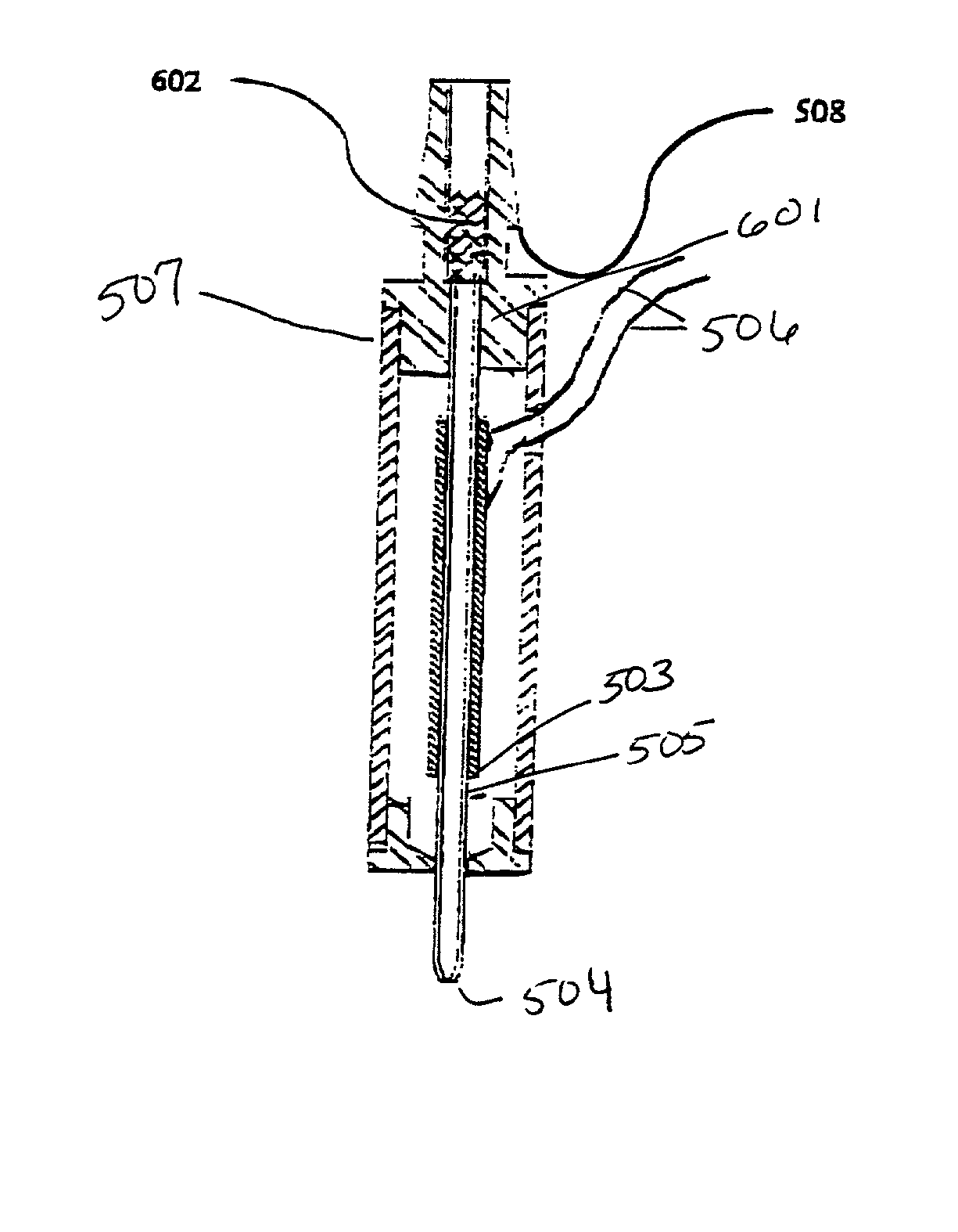
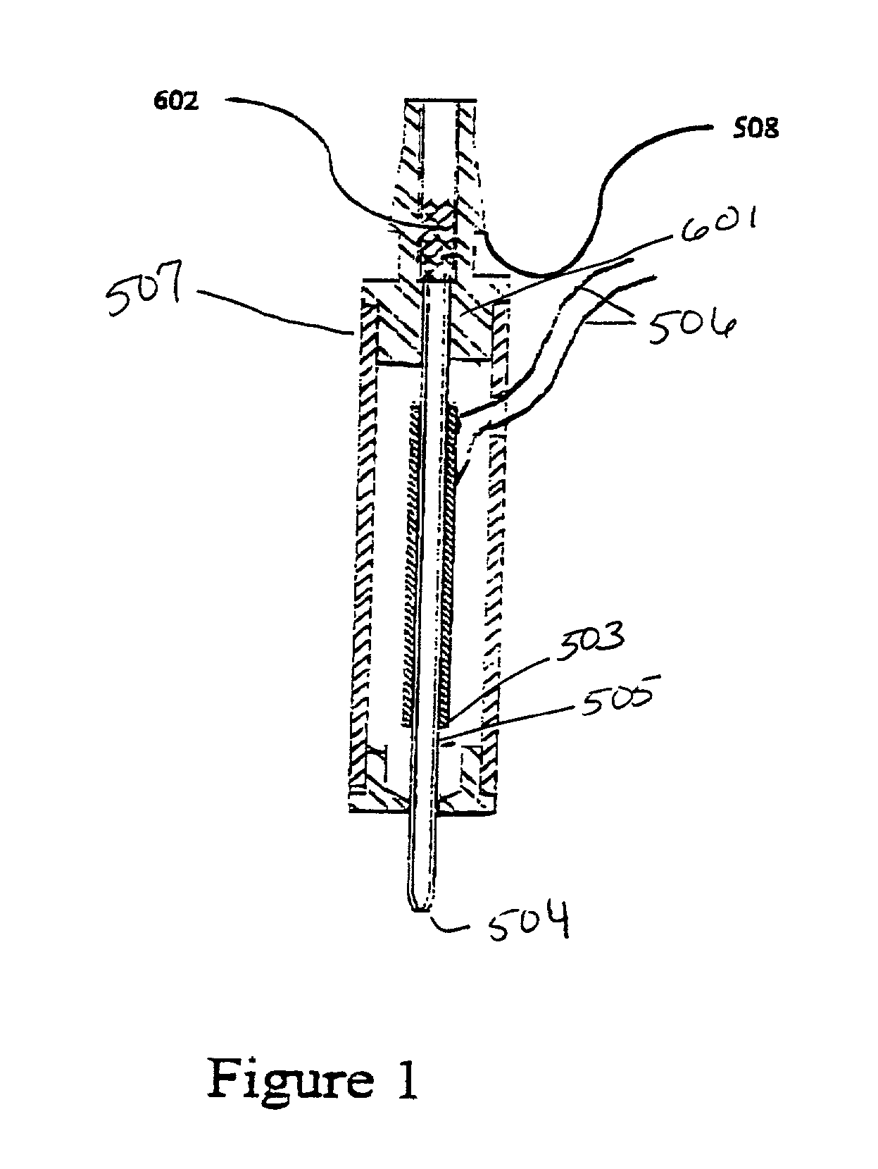
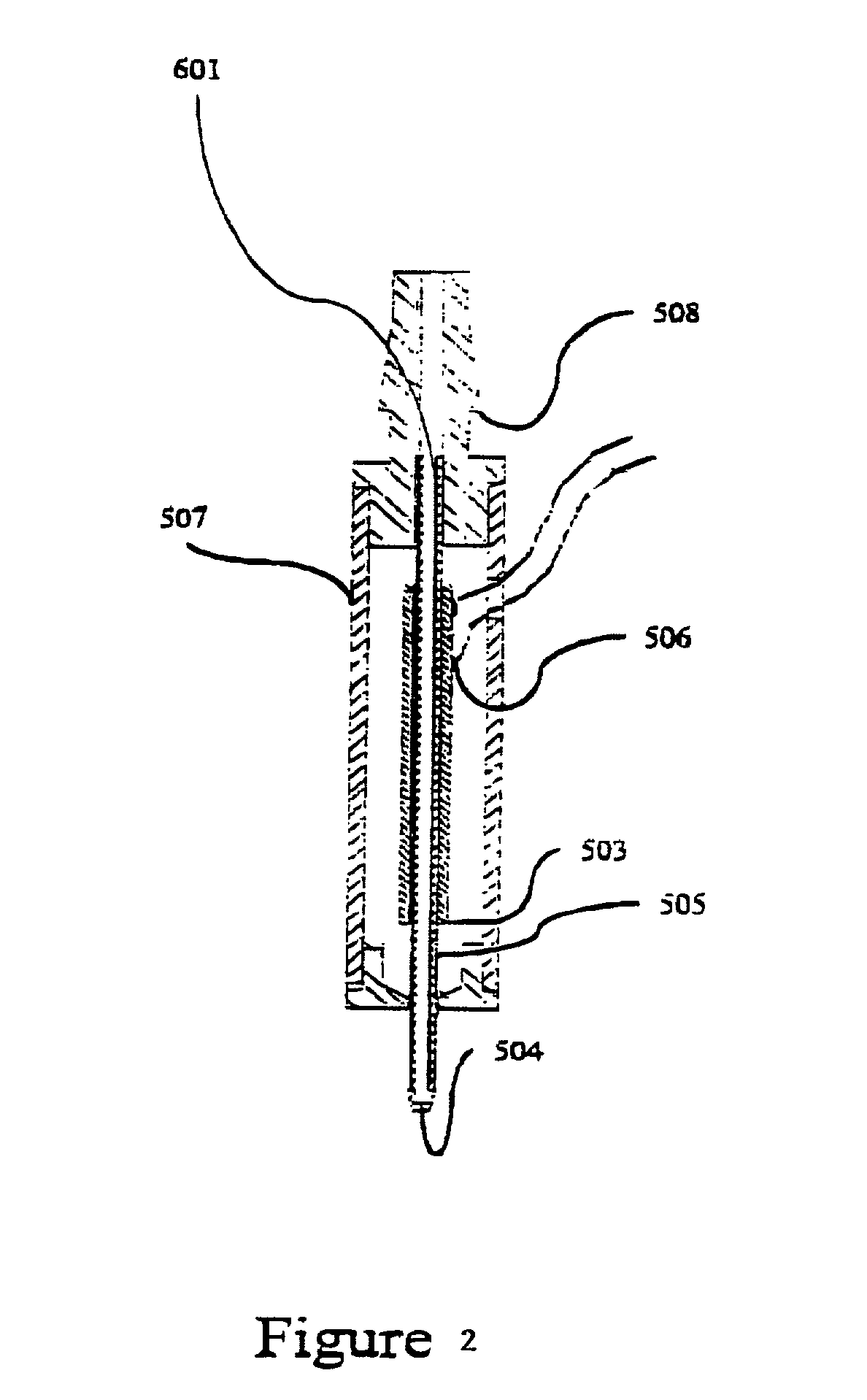
[0051] An embodiment of a type of microdispensing device is where collecting means in the form of chromatography packing material is connected to the aperture of the microdispensing device is shown in FIG. 1. A PZT tube (503) is concentrically bonded with a glass capillary jetting tube (505), which comprises an orifice (504) at one end. The leads (506) on the PZT electrodes are for electric connections. This unit is housed within a case (507). A barbed ferrule (508) provides fluid connection, and connects to the LC resin collecting material (601). The length of the collecting material (601) is variable, depending on the requirement of compound separation. The length of the PZT tube (503), and also the length of the glass capillary jetting tube (505), is selected to balance the trade-off between the reduction in dead volume and the gain in piezoelectric driving efficiency (a short tube has smaller dead volume and lower driving efficiency, and visa versa).

[005...


PUM

PropertyMeasurementUnit
Capillary waveaaaaaaaaaa
Pressureaaaaaaaaaa
Volumeaaaaaaaaaa

Abstract

A microdispensing apparatus comprising a jetting tube comprising an orifice at one end and an aperture at the other end, a transducer coupled with the jetting tube and adapted to apply a pressure pulse to the jetting tube in response to an electrical signal applied to the transducer such that liquid in the jetting tube is caused to pass therethrough, and means for collecting, capturing or retaining one or more compounds from liquid passing the jetting tube; a system for sampling, collecting and dispensing compounds in small volumes of liquid including the microdispensing apparatus; and methods of sampling, collecting and arraying small quantities of compounds in a liquid sample on a target.

Description

[0001] This application is a continuation-in-part and, thus, claims the benefit of priority under 35 U.S.C. .sctn.120 of PCT Application No. PCT / AU00 / 00688, filed Jun. 19, 2000 and published in English on Dec. 28, 2000 as WO / 0079238; which claims priority to Australian Application No. PQ1055, filed Jun. 18, 1999. The disclosure of the prior applications is considered part of and is incorporated by reference in their entirety to the present application.[0002] The invention relates to apparatus and methods for separating and analyzing compounds, particularly biomolecules using a microdispensing apparatus and systems.[0003] Sensitivity and specificity of analysis of compounds is improving due to the development of highly sensitive systems for analysis. Unfortunately, the development of systems to handle very small volumes of compounds in extremely low concentrations has not kept up with the analysis technology. There are many situations where only small amounts of sample, containing li...

Claims


Application Information

Patent Timeline
IPC IPC(8): B01L3/02G01N27/62C12M1/00C12Q1/68G01N1/00G01N30/00G01N30/72G01N30/88G01N35/10H01J49/04
CPCB01L3/0268G01N2030/009H01J49/04Y10T436/24Y10T436/2575
Inventor WALLACE, DAVIDCHEN, TINGGOOLEY, ANDREW ARTHURHOPWOOD, FEMIA
Owner PROTEOME SYST LTD
Learn More