Dual damascene horn antenna

a damascene and horn technology, applied in the direction of antennas, slot antennas, waveguide horns, etc., can solve the problem of damascene processing of ic chips incurring lower production costs

Inactive Publication Date: 2002-10-17
GLOBALFOUNDRIES US INC
View PDF0 Cites 12 Cited by
  • Summary
  • Abstract
  • Description
  • Claims
  • Application Information

AI Technical Summary

Problems solved by technology

Use of damascene processing of IC chips incurs lower-production costs since comparable discrete components typically require more processing steps.

Method used


Image

  • Dual damascene horn antenna
  • Dual damascene horn antenna
  • Dual damascene horn antenna

Examples


Embodiment Construction

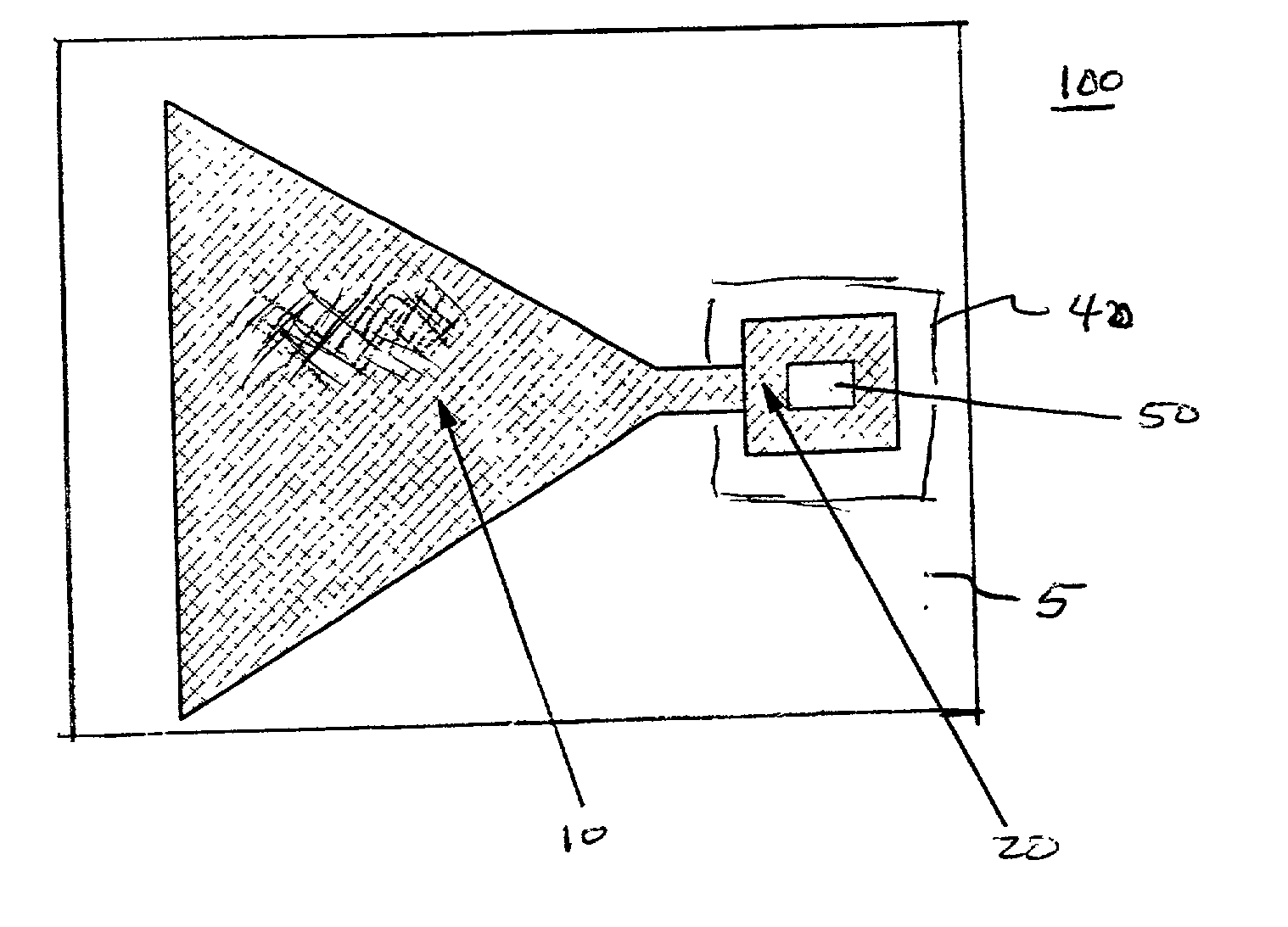
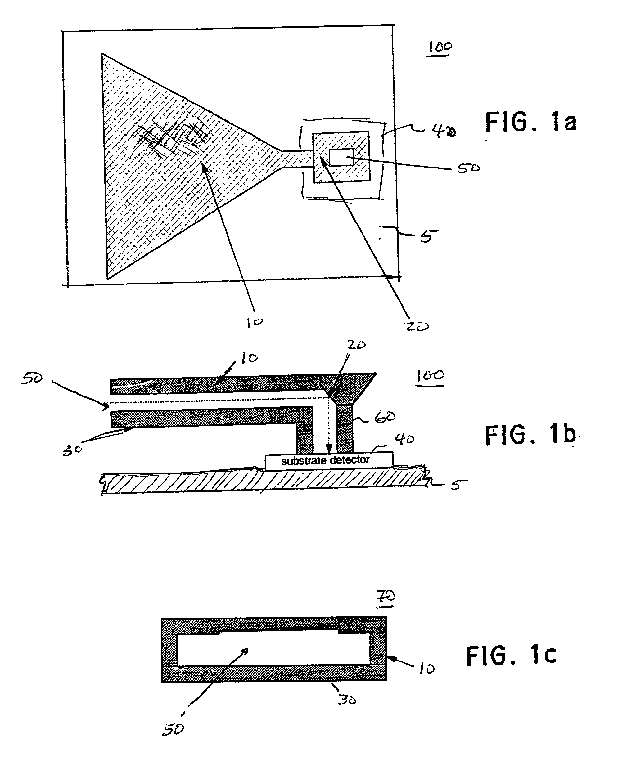
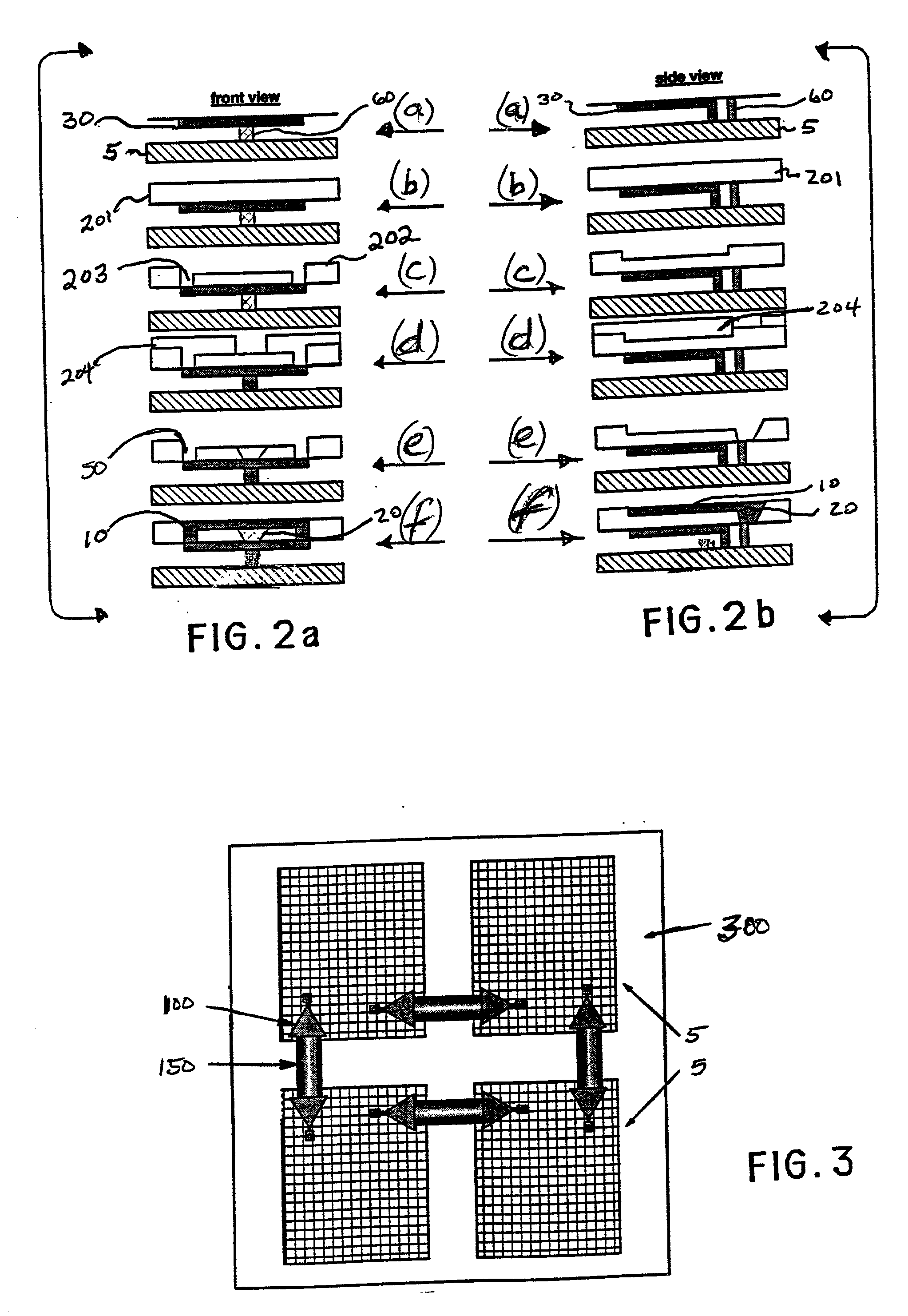
[0020] Referring now to FIGS. 1a, 1b and 1c, a horn antenna device 100 is shown. This device is used for chip-to-chip communications using RF, microwave, infrared, or visible EM spectral bands. The device can be either a stand-alone structure or form part of an array that are mounted on chip-edges (see below and shown in FIG. 3), wherein each horn antenna device is part of a multiple transceiver network on a common module. A sequence of dual damascene fabrication steps are shown in FIGS. 2a and 2b of the horn antenna device that is made concurrently with the wiring / interconnects on an IC chip.

[0021] FIGS. 1a, 1b and 1c show a top, side, and frontal-views of an exemplary form of the device 100. An upper sectional horn antenna structure 10 and a bottom horn sectional structure 30 together formed using metal damascene construction form a horizontal waveguide section 70 having a tapered via 50, preferably with a 45-degree tapered opening section. This waveguide section 70 in turn commun...


PUM


Abstract

An integrated horn antenna device with an integrated circuit (IC) chip including a metallic horn structure having a wide aperture, a horizontal waveguide with a tapered via that electromagnetically communicates with a vertical waveguide structure to transmit energy to and from an electronic sub-component transceiver device forming part of the IC chip. Another embodiment of the invention comprises a plurality of multiple discrete IC chips having the integrated horn antenna devices incorporated therewith forming a module for data transmissions between these IC chips. Another embodiment of the invention includes additional external waveguide structures such as optical fibers external to the chips, where radiation is aligned between the horn structures and these waveguides. Dual damascene processing is used to fabricate the horn antenna device within the IC chip.

Description

[0001] 1. Field of the Invention[0002] The present invention generally relates to antenna structures used with integrated circuits (IC), and particularly to a horn antenna that is integrated with waveguides and other components, which is made by a dual damascene technique.[0003] 2. Description of the Related Art[0004] Electromagnetic(EM) waveguides (including antennae) are structures that confine and guide EM energy from one physical location to another. A hollow EM waveguide is typically a conductive tube-like structure, wherein a horn antenna is a tapered or flared structure that couples energy to or from free space and concentrates the energy within a defined beam pattern. Only the inside structure of these antenna devices need be conductive so as allow current within a skin depth of the metallic surface, which is related to wavelength of the transmitted energy. Dimensions of these structure are also dependent on characteristic wavelength of radiation transmitted through these st...

Claims


Application Information

Patent Timeline
Patent Type & Authority Applications(United States)
IPC IPC(8): H01P11/00H01Q21/28H01Q1/22H01Q1/38H01Q13/02H01Q13/06
CPCH01Q13/0283
Inventor BALLANTINE, ARNE WATSONEDELSTEIN, DANIEL CHARLESNAKOS, JAMES SPIROSSTAMPER, ANTHONY KENDALL
Owner GLOBALFOUNDRIES US INC
Why Eureka
Try Eureka