Air-conditioning system with thermal storage

a technology of air-conditioning system and thermal storage, which is applied in the direction of refrigeration machines, machines/engines, process and machine control, etc., can solve the problems of difficult thermal stratification, high cost of pebble bed stone, and high cost of insulating storage tanks for holding water and maintaining temperature, so as to achieve maximum storage capacity

Inactive Publication Date: 2002-12-05
WORK SMART ENERGY ENTERPRISES
View PDF1 Cites 21 Cited by
  • Summary
  • Abstract
  • Description
  • Claims
  • Application Information

AI Technical Summary

Benefits of technology

0075] 5) Achieves thermal stratification to maximize storage capacity, and

Problems solved by technology

Unfortunately, while water itself is inexpensive, the insulated storage tanks necessary for holding the water and maintaining its temperature are quite expensive, typically a $1 per gallon or more.
A secondary problem is water mixes very easily in a storage tank, which makes it difficult to achieve thermal stratification.
The stone necessary for a pebble bed is has a significant cost and the space requirements mean that this type of storage can take a large portion of a basement or other part of building.
In addition to the problems discussed above, the size requirements can be of the tank can be quite large because of the limited temperature differential available between the freezing point of water and the temperature required for useful cooling and dehumidification of the space (typically .about.20.degree. F.).
Unfortunately making ice requires low evaporating temperatures from the refrigeration systems to reach the freezing point of water and to overcome the thermal resistance of ice that forms on heat exchanger surfaces.
These problems reduce the efficiency and increase the cost for ice storage.
Unfortunately, these materials are usually quite expensive and frequently have problems very slow freezing rates, which create additional problems beyond those found with ice storage.
Toxicity of materials can also be a concern in some cases.
This arrangement does not allow direct use of water from the enclosure for directly cooling a building, and instead proposes rejecting heat from the heat pump to the enclosure during the cooling season.

Method used


Image

  • Air-conditioning system with thermal storage
  • Air-conditioning system with thermal storage
  • Air-conditioning system with thermal storage

Examples


Embodiment Construction

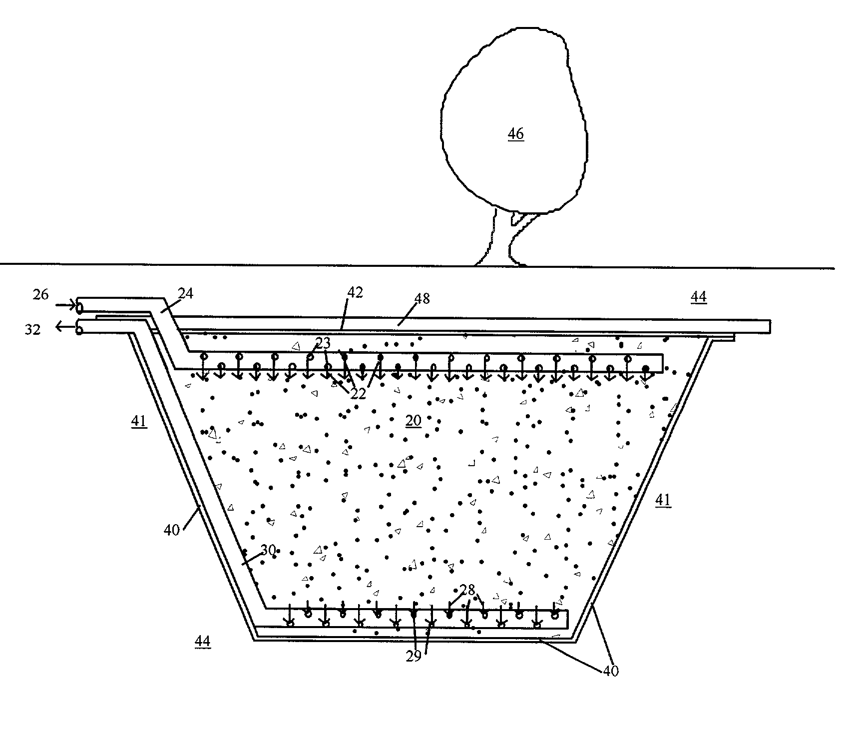
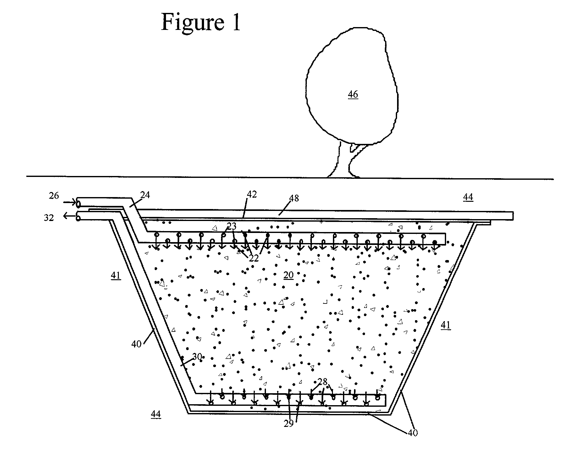
[0027] FIG. 1 is a preferred embodiment of the invention. A pipe 24 provides a flow path for warm liquid 26. The liquid is preferably water or a dilute aqueous solution. As shown in figure warm liquid 22 the pipe 24 through holes 23 and flows into a bed of permeable material 20, which acts as a fill material. A pool of liquid preferably fills the voids in the bed of permeable material 20. Cool liquid 28 exits the bed of porous material 20 through holes 29 in pipe 30 that provides a flow path for cool liquid 32.

[0028] A bottom liner 40 ensures that liquid stays in the bed of porous material. A top liner 42 prevents surface or ground water from entering the bed. The liner material is preferably a tough, impermeable, plastic material such as those used for liners for ponds or landfills.

[0029] The liner preferably prevents leakage of liquid and provides little or no structural support. Impermeable clay or similar material can also be used as a liner instead of plastic. A thin layer of c...


PUM

PropertyMeasurementUnit
temperatureaaaaaaaaaa

Abstract

An air-conditioning system with thermal storage system for storing cooling capacity. The storage system comprises a quantity of fill material that preferably comprises water or similar liquid that is located in a cavity in the ground. The fill material may also include a bed of gravel with the pool of liquid filling the void spaces in the gravel. Sidewalls of the cavity are preferably supported primarily by the mechanical properties of the earth and the fill material. The lower boundary of the cavity is impermeable liner. A cover that blocks solar radiation and preferably with thermal insulation covers the top of the fill material. A chiller and a pump supply cooled liquid during night or other times of reduced electrical costs and liquid from the storage flows through a liquid-to-air heat exchanger during peak demand periods.

Description

[0001] Applicant claims benefit of co-pending provision application No. 60 / 285,512 filed on Apr. 20, 2001.[0002] 1. Field of the Invention[0003] The invention in the field of thermal-storage devices that are suitable for use in air-conditioning systems.[0004] 2. Description of Prior Art[0005] Thermal storage for space cooling and heating has a long history. Passive systems for buildings using massive masonry walls have been used for millennia in dry climates to provide a more-even interior temperature despite large swings in ambient temperatures.[0006] Active thermal storage has been used for solar heating systems. Two types of thermal storage are common in these systems. The first type is storage use using insulated tanks of water. Water has the advantage of having high specific heat and the ability to store a large amount of heat in small volume, which reduces storage size. Unfortunately, while water itself is inexpensive, the insulated storage tanks necessary for holding the wate...

Claims


Application Information

Patent Timeline
Patent Type & Authority Applications(United States)
IPC IPC(8): F24F5/00F25D17/02F28D20/00
CPCF24F5/0017F25D17/02F28D20/0043F28D2020/0013Y02E70/30Y02B10/24Y02E60/142Y02E60/147Y02B10/20Y02E60/14
Inventor KOPKO, WILLIAM L.
Owner WORK SMART ENERGY ENTERPRISES
Why Eureka
Try Eureka