Method for depositing a coating on the wall of metallic containers

Inactive Publication Date: 2002-12-05
CEBAL SA
View PDF6 Cites 25 Cited by
  • Summary
  • Abstract
  • Description
  • Claims
  • Application Information

AI Technical Summary

Benefits of technology

0022] Similarly, when carbon deposition is carried out, it is preferable to mix the selected precursor (e.g. acetylene) with one of the gases mentioned above (HMDSO, TMDSO, tributyl aluminium) so as to obtain enhanced barrier properties. For depositions carried out on container blanks intended for subsequent deformation, the mixture is determined such that the aluminium or silicon content of the deposit is approximately or less than 5%. This consists of improving the adherence of the deposit on the substrate but not degrading the ductile properties of the deposit excessively and thus preventing peeling during the subsequent deformation.
0023] Said method offers the advantage of being possible at a pressure close to atmospheric pressure, preferentially between 200 and 760 millimeters of mercury. A slightly lower pressure than atmospheric pressure enables better control of the purity of the gas circulating in the container. Prior flushing is preferentially carried out with an inert gas, such as argon to prevent the formation of impurities (risk of reaction with nitrogen in air, water vapour, etc.) liable to deteriorate the quality of the adherence of the layer deposited.
0024] In

Problems solved by technology

Said contact may be maintained for several years under relatively high temperature conditions specified within the scope of the use of this type of packaging (approximately 50.degree. C.) and such conditions make it impossible to prevent a certain susceptibility to corrosion, irrespective of

Method used


Image

  • Method for depositing a coating on the wall of metallic containers
  • Method for depositing a coating on the wall of metallic containers
  • Method for depositing a coating on the wall of metallic containers

Examples


Example

EXAMPLE 2

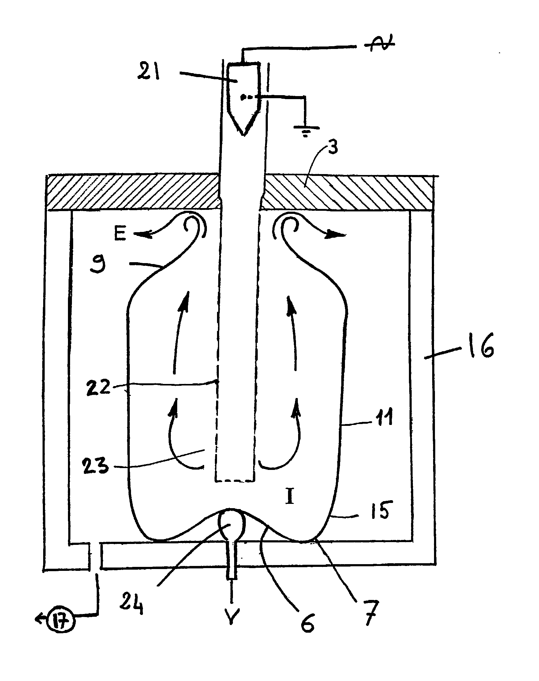
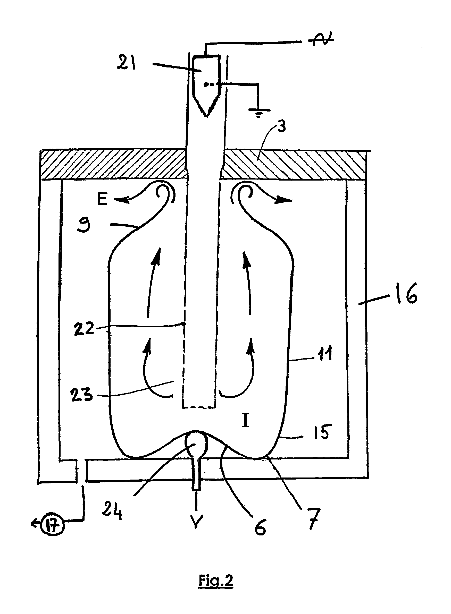
Deposition of a Mixed Carbon with Polymeric Tendency and Silica Coating on the Inner Wall of an Aerosol Container Blank (FIG. 3)

[0041] This example illustrates the first alternative embodiment of the invention. It consists of the deposition of a coating on the inner surface of containers in the middle of the production line, i.e. at a stage when the container is not yet coned. This stage is located in the production line exactly at the current varnish deposition stage of the prior art, which this method proposes to replace.

[0042] The electrode 32 has a shape fitting to within 2 mm the shape of the inner surface of a drawn extruded container blank 1. It is coated with a 20 .mu. layer of polypropylene. The base of the blank has already been shaped: it comprises a toric base 7 surrounding a concave dome 6. The electrode is pierced with a duct 31 used to supply the precursor gas P in the air gap between the electrode and the container.

[0043] The container is placed inside a cou...

Example

EXAMPLE 3

Deposition of an Alumina Coating on the Inner Wall of an Aerosol Container Blank

[0045] This example corresponds to the third alternative embodiment of the invention, where the deposition is carried out by corona discharge at the end of the production line, on already coned containers.

[0046] An electrode of a suitable shape is introduced into the opening: its orthogonal section has a contour comprising a large number of convexities and acute angles oriented outwards, but its outer contour has a diameter less than that of the opening (25.4 mm). As such, the metal electrode may be introduced easily into the already coned container (diameter of cylindrical body of container: 45 mm) and comprises longitudinal convexities and edges oriented towards the inner wall of the container.

[0047] The electrode is hollow, which makes it possible to supply the inside of the container with precursor gas. A tributyl aluminium (10%) argon (85%) and oxygen (5%) mixture is injected as the precurs...


PUM

PropertyMeasurementUnit
Lengthaaaaaaaaaa
Lengthaaaaaaaaaa
Pressureaaaaaaaaaa

Abstract

The invention relates to a method for depositing a coating on the wall of a metal container. According to said method, the coating is deposited using a plasma at a pressure close to atmospheric pressure. The metallic container can be an aerosol dispenser can and the resulting coating advantageously replaces the internal layer of varnish usually deposited in containers of this type.

Description

[0001] The invention relates to a method enabling the deposition of a coating protecting the inner or outer surface of metal containers. Said containers are intended to contain liquid to pasty products such as pharmaceutical, parapharmaceutical, cosmetic and nutritional products. They may consist of dispensers of products in aerosol, foam or gel form using a pressurised gas.STATE OF THE RELATED ART[0002] Metal containers protect the products they contain from outside contamination or a degradation of their formulation by evaporation of one of their ingredients. The metal wall is an excellent diffusion barrier for gases and aromas. However, it is often preferable for this wall to be in direct contact with said products. Said contact may be maintained for several years under relatively high temperature conditions specified within the scope of the use of this type of packaging (approximately 50.degree. C.) and such conditions make it impossible to prevent a certain susceptibility to co...

Claims


Application Information

Patent Timeline
IPC IPC(8): B05D7/22B05D7/24C23C16/04C23C16/40
CPCB05D1/62B05D7/227Y02T50/67C23C16/402C23C16/403C23C16/045Y02T50/60
Inventor BEN-MALEK, MOHAMEDJUPIN, ALAIN
Owner CEBAL SA
Why Eureka
Try Eureka