
Spacer - connector stud for stacked surface laminated multichip modules and methods of manufacture

a technology of spacer and connector stud, which is applied in the direction of printed circuit structure associations, solid-state devices, basic electric elements, etc., can solve the problem that the prior art does not disclos

Inactive Publication Date: 2003-02-27
IBM CORP
View PDF0 Cites 13 Cited by
  • Summary
  • Abstract
  • Description
  • Claims
  • Application Information

AI Technical Summary

Benefits of technology

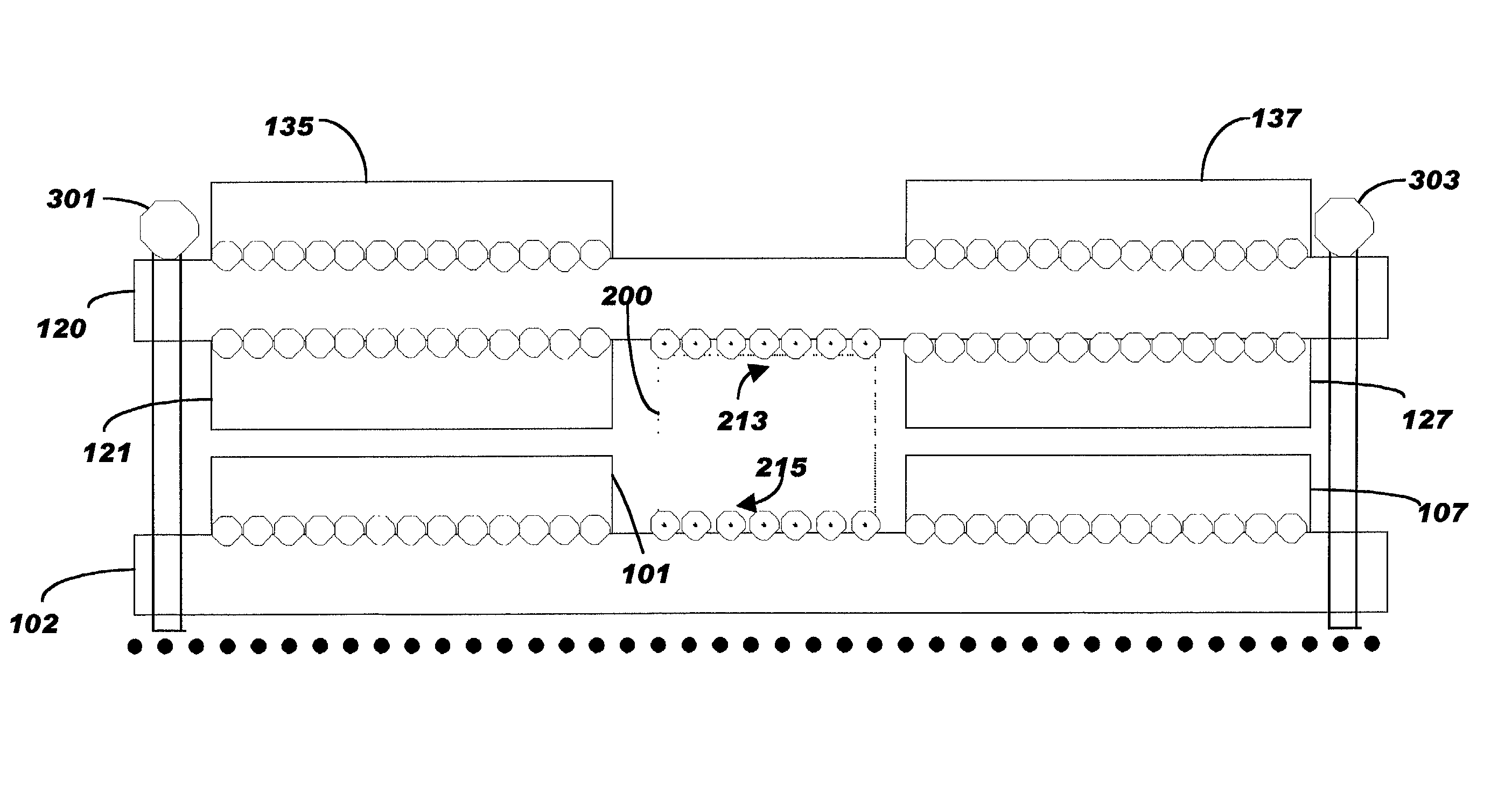
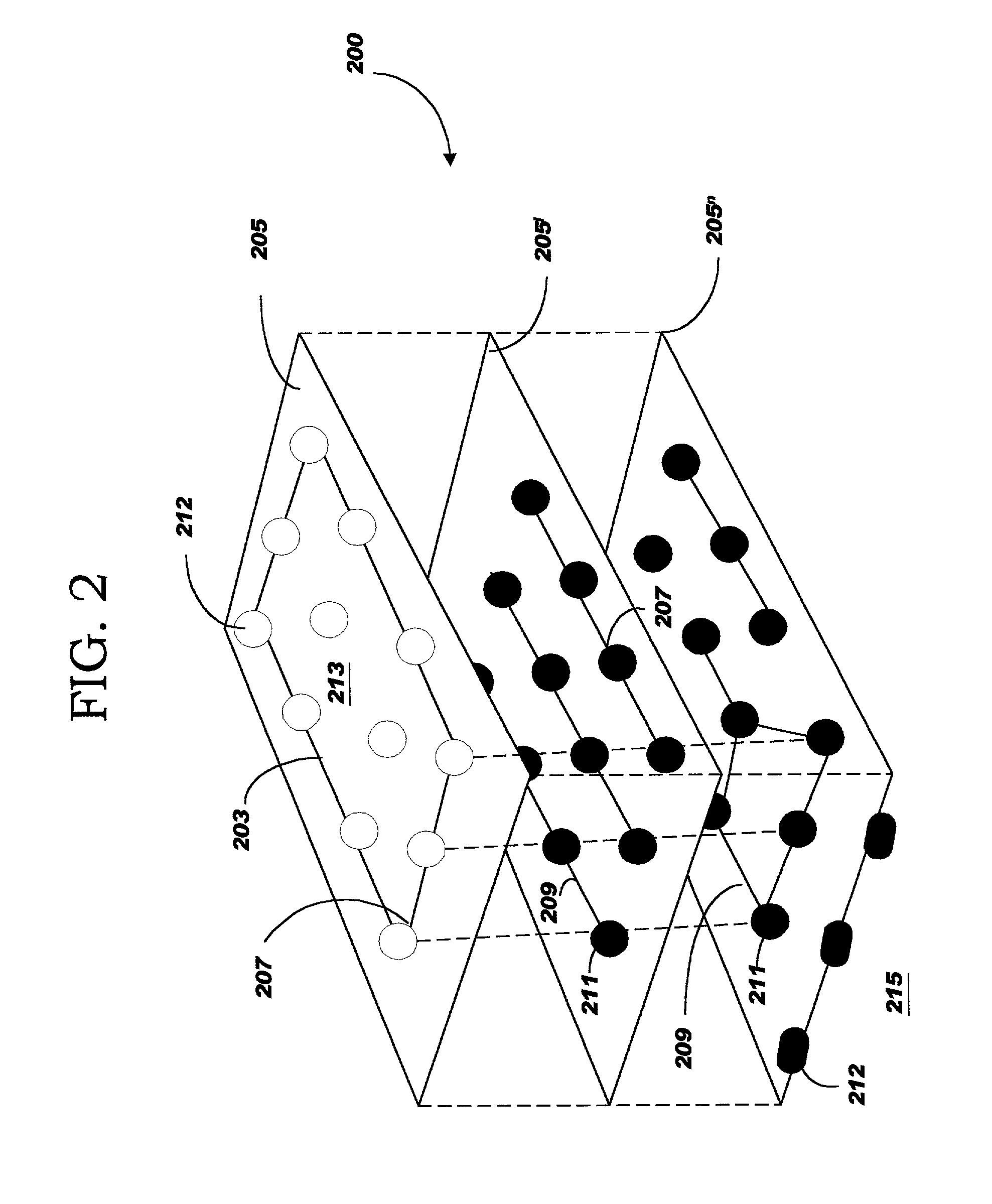
[0010] A stacked array of multi-chip modules cards are interconnected through a surface laminated stud which serves as an interconnector and spacer for the stacked multi-chip modules cards. The stud comprises a stacked array of glass epoxy laminates, each laminate having a copper layer laminated thereto. A circuitization pattern is formed in the copper layer by selected etching. Drilled and plated through holes within the laminates can carry many signals between laminates plus power and ground lines. A photosensitive thermal-setting resin insulating layer is applied atop the wiring layer. The resin-insulating layer is formed by applying a solution of soluble photosensitive, thermal-setting resins in a solvent atop the wiring layer. The solvent resins are evaporated by a pre-cure heating. The heating step serves to drive off the solvent and solidify the resins' insulating layer. The resin layer is planarized by abrasion. The top and bottom laminates of the stud may include a spatial array of thermal contacts suitable for C4 bump technology. A location is selected on the card to accommodate the laminated stud. The thickness of the stud is greater than twice the thickness of the components attached to the card The thermal contacts on the stud, typically solderable, join to the circuit patterns on the multi-chip module card. A second multi-chip module card having components on top and bottom surface is mechanically aligned and pressed against the contacts on top surfaces of the stud to form an assembly. The assembly can be heated causing the second card to become soldered to the contact footprint on the stud. A solder hierarchy may be employed such that overlying circuit board and stud does not reflow when the bottom surface of the stud is joined to the underlying circuit board.

Problems solved by technology

None of the prior art discloses a stacked array of SLC multi-chip modules including a spacer and interconnector comprising at least two glass-epoxy dielectric laminates with interconnecting circuit patterns for spacing and interconnecting the SLC multi-chip modules without disturbing any of the existing connections between the multi-chip modules and the SLC boards.

Method used


Image

  • Spacer - connector stud for stacked surface laminated multichip modules and methods of manufacture
  • Spacer - connector stud for stacked surface laminated multichip modules and methods of manufacture
  • Spacer - connector stud for stacked surface laminated multichip modules and methods of manufacture

Examples


Embodiment Construction

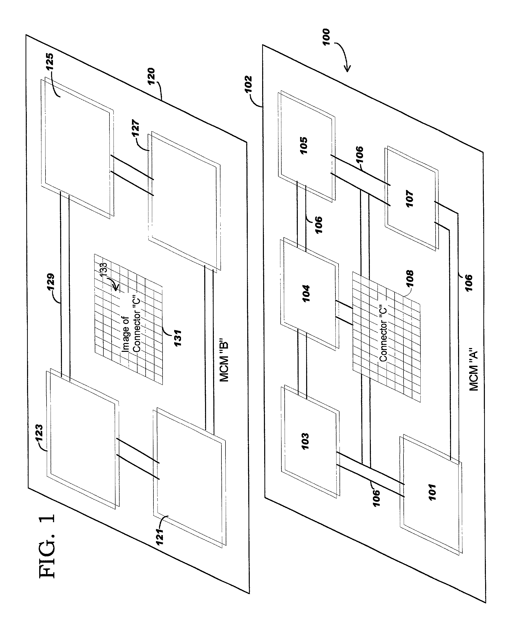
[0015] In FIG. 1, a multichip module circuit board 100 comprises a dielectric member 102. In one embodiment, the member is a glass epoxy substrate, covered by a copper layer which is patterned by selective etching to form a wiring layer, including a signal wiring conducting layer 106. A photosensitive thermal setting resin in a solvent is applied to the surface to form an insulating resin layer. The solvent is evaporated from the resin by a pre-cure heating, followed by an exposure and development step to form photo via holes in the board. Thereafter, the resin is cured and the surface of the resin layer is planarized by grinding to provide a flat surface for subsequent processing as circuitization. The process for forming the substrate is more fully described in U.S. Pat. No. 5,766,825 assigned to the assignee of the present invention and fully incorporated herein by reference.

[0016] An assembly of components, 101, 103, 104, 105 and 107 are attached to the circuit board 102, using ...


PUM


Abstract

A spacer-connector stud comprises a stacked array of glass epoxy laminates, each laminate having a copper layer laminated thereto. The top and bottom laminates of the stud include a spatial array of thermal contacts suitable as a footprint for C4 bump technology. A location is selected on a circuitized base card to accommodate the laminated stud. The stud has a thickness greater than twice the thickness of the components attached to the card. The thermal contacts on the stud, typically solderable, join to a wiring array on the card. A second multi-chip module card having attached and interconnected components on both sides of the second card is mechanically aligned with the based card and pressed against the contacts on the top layer of the stud to form an assembly. The assembly is heated causing the second card to become soldered to the contact footprint on the stud.

Description

BACKGROUND OF INVENTION[0001] 1. Field of Invention[0002] This invention relates to surface laminated circuit (SLC) components, and methods of manufacture. More particularly, the invention relates to spacer-connector studs for stacked SLC multi chip modules and methods of manufacture.[0003] 2. Description of Prior Art[0004] A Surface Laminated Circuit (SLC) printed circuit board has successively laminated copper clad glass-epoxy laminations as a substrate. A photosensitive epoxy resin serves as an insulating layer and a copper plated layer as an external-conducting surface. SLC type circuit boards are described in U.S. Pat. No. 5,766,825 assigned to the assignee of the present invention and fully incorporated herein. Electronic components, e.g. Random Access Memory (RAM); Read Only Memory (ROM); Integrated Circuits (IC), etc. may be modularized and attached to the upper and lower surfaces of the SLC board by solder ball reflow joining techniques. The attached modules may be intercon...

Claims


Application Information

Patent Timeline
Patent Type & Authority Applications(United States)
IPC IPC(8): H01L25/10H05K1/14
CPCH01L25/105H01L2924/3011H05K1/144H01L2924/0002H01L2924/00
Inventor COHN, DAVID LESLIEMCBRIDE, DENNIS JAYMONTOYE, ROBERT KEVIN
Owner IBM CORP
Learn More