
Electron-cyclotron resonance plasma reactor with multiple exciters

a plasma reactor and electron cyclotron technology, applied in the field of electron cyclotron resonance plasma reactors, can solve the problems of difficult control of the uniformity of the rf (radio frequency) energy pattern, difficult to meet the needs of semiconductor manufacturing of the future, and complicated main magnet and cooling system of conventional ecr

Inactive Publication Date: 2003-04-03
NI HAO JAN
View PDF5 Cites 16 Cited by
  • Summary
  • Abstract
  • Description
  • Claims
  • Application Information

AI Technical Summary

Problems solved by technology

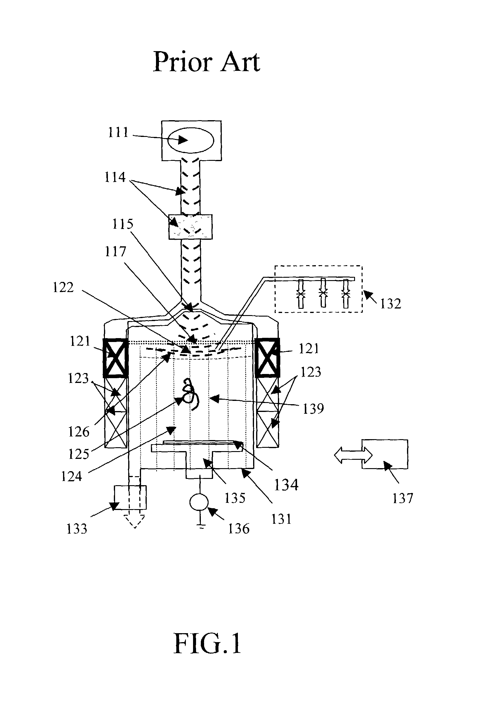
But conventional ECR needs a very complex Main Magnet and cooling system.
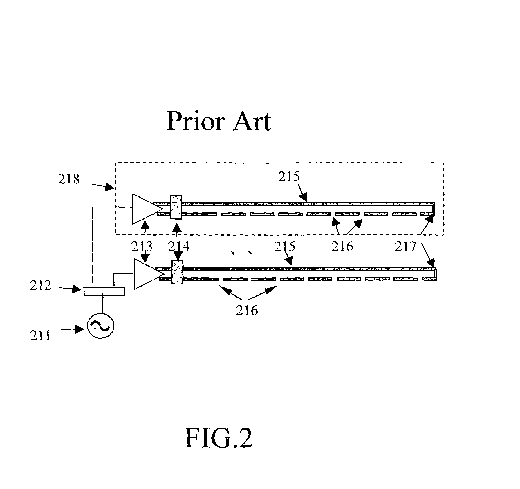
It is also very difficult to control the uniformity of RF (Radio Frequency) energy pattern, especially for large-sized ECR.
Under these limitations, the conventional ECR is hard matching the tomorrow's needs of the semiconductor manufacturing, especially on large-sized wafer.
The Main Magnet of Conventional ECR is inefficient.
By the way, the cooling system for the complex Main Magnet, the centralized high-powered RF source, and the pattern of the RF energy control with large area limit the applications of Conventional ECR on large wafer size.
How to feed high-powered RF energy is one of the key issues on ECR design.

Method used


Image

  • Electron-cyclotron resonance plasma reactor with multiple exciters
  • Electron-cyclotron resonance plasma reactor with multiple exciters
  • Electron-cyclotron resonance plasma reactor with multiple exciters

Examples


Embodiment Construction

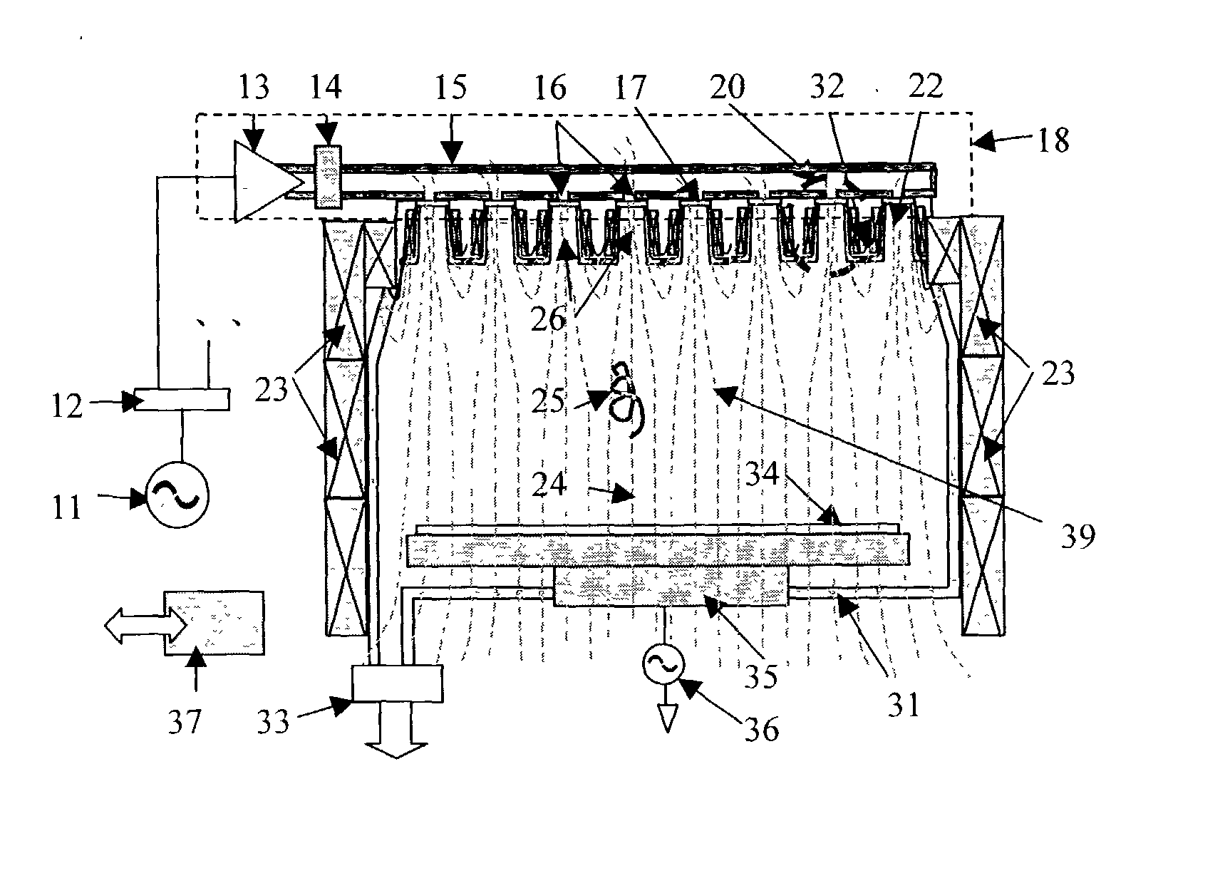
are shown in FIG. 3 to FIG. 6. The following details are used the same element number in those figures.

[0042] Referring to FIGS. 3 to 6, the Wafer (34) is fixed on the top of the Wafer Pedestal (35). All of them are placed in a Reaction Chamber (31). The Reaction Chamber (31) maintains in very low pressure by a Vacuum Pump (33) from its outlet. The Wafer Pedestal (35) is set at the bottom of the Reaction Chamber and is adjustable for modifying the distance between the wafer (34) and the top of the Reaction Chamber (31), and for controlling ion density or energy near the wafer (34).

[0043] The plural reactant gas (27, 32) is introduced into the Reaction Chamber (31). Each of them comprises a valve apparatus for individually supplying gas and controlling gas flow rates individually. Functionally, There are two kinds of gas, one is the Operation Gas (27), i. e. Argon, and the others are the Process Gas (32). The Operation Gas (27) is used in each RECC (22) to generate high-speed electro...


PUM

PropertyMeasurementUnit
Dielectric polarization enthalpyaaaaaaaaaa
Flow rateaaaaaaaaaa
Magnetic fieldaaaaaaaaaa

Abstract

An Electron-Cyclotron Resonance (ECR) Plasma Reactor with Multiple Exciters is disclosed. The exciters relate to a mechanism that converts the radiation energy to the electron's kinetic energy. With using a suitable antenna distributes the RF energy to distinguished exciter individually, each exciter has its own magnetic coil to build high magnetic field to resonance the electron of the operation gas, ionize the gas and generate high speed electrons. All of the high-speeded electrons can be guided by magnetic flux and accumulated to the remained part of the reaction chamber. There is an auxiliary magnet to cause energized electron moving in a helix path. The helix path makes more chance of the collision between the electron and the process gas. When collision occurs, the electron's kinetic energy activates the process gas and high-density plasma or radicals generated. The auxiliary magnetic field is also used for controlling the uniformity of plasma near the wafer pedestal area. This is a distributed ECR system with multiple RF energy conversion mechanisms, the "exciters". It simplifies the total system complexity by discrete but simpler main magnets, cooling system, low power RF energy sources etc. The invention gives an easy way to build a large-sized ECR just by increasing the number of exciters.

Description

[0001] 1. Field of Invention[0002] The invention relates to an Electron-Cyclotron Resonance System and, in particular, to an Electron-Cyclotron Resonance Plasma Reactor with Multiple Exciters.[0003] 2. Related Art[0004] Plasma is widely used in semiconductor manufacturing process. Among the plasma generation methods, Electron-Cyclotron Resonance (ECR) is the most potential technology for tomorrow's IC industry. ECR generates a high density, low temperature and high quality plasma. It can operate in very low pressure, e.g. 0.1 m-torr. In such low pressure, the probability of collision between ions is very low, so that the plasma has very good an-isotropic performance, which can make ECR as the best tools for dry etching and other applications as well.[0005] But conventional ECR needs a very complex Main Magnet and cooling system. It is also very difficult to control the uniformity of RF (Radio Frequency) energy pattern, especially for large-sized ECR. Under these limitations, the con...

Claims


Application Information

Patent Timeline
IPC IPC(8): H01J37/32
CPCH01J37/32678H01J37/32192
Inventor NI, HAO-JAN
Owner NI HAO JAN
Learn More