Supercharge Your Innovation With Domain-Expert AI Agents!

Method of measuring wavelength dispersion amount and optical transmission system

Inactive Publication Date: 2003-04-17
FUJITSU LTD
View PDF4 Cites 48 Cited by
  • Summary
  • Abstract
  • Description
  • Claims
  • Application Information

AI Technical Summary

Problems solved by technology

Because, as described above, the number of WDM wavelengths has increased to several hundreds of channels, it becomes necessary to prepare transponders (devices to perform optical / electrical conversion, reproduce a signal, perform conversion of a modulation format and a wavelength, and connect to another device) for the number of wavelengths at the transmission and reception nodes, thereby increasing costs.
Therefore, waveform distortion (pulse broadening) due to wavelength dispersion gives rise to intersymbol interference, and this in turn is a factor limiting transmission lengths.
However, in the cases of the optical add-drop method shown in FIG. 24B, and in the optical cross-connect method shown in FIG. 24C, it is anticipated that application of a technique like those described above will be difficult, for the following reasons:
This, however, limits the freedom of switching configurations; and because major changes in optical fiber characteristics due to path switching are conceivable, as for example when changing from single-mode fiber (SMF) to nonzero dispersion shifted fiber (NZDSF), it is difficult to adjust the wavelength dispersion amount of all paths to zero.
Further, it is unrealistic to attempt to measure wavelength dispersion amount in advance for all of a huge number of paths; and in cases where new paths are added, measurements for all the newly added paths must be performed once again.
In such cases there is a problem that lines in use must be temporarily interrupted.
Accordingly, in order to completely compensate for the wavelength dispersion amount, a design must also take into consideration the accumulated shifts in such wavelength dispersion amounts; however, it is extraordinarily difficult to perform complete dispersion compensation for all routes, while also taking wavelength dependency into account.
For the above reasons, there has been a problem that current methods for designing dispersion compensation amount cannot easily be applied to WDM optical transmission systems incorporating the functions of optical add-drop or optical cross-connect methods.

Method used


Image

  • Method of measuring wavelength dispersion amount and optical transmission system
  • Method of measuring wavelength dispersion amount and optical transmission system
  • Method of measuring wavelength dispersion amount and optical transmission system

Examples


Embodiment Construction

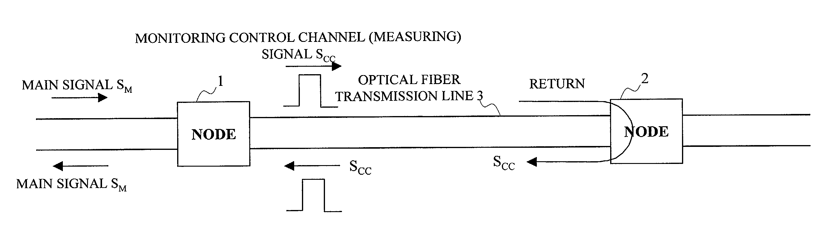
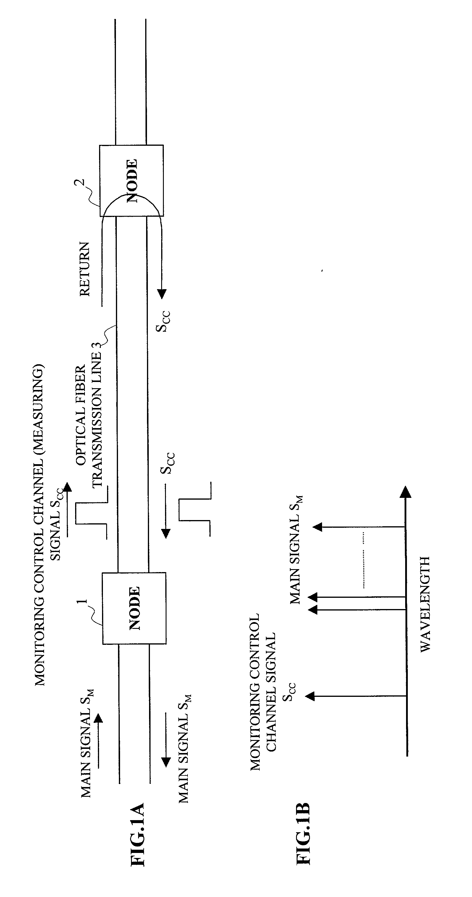
[0099] FIGS. 1A and 1B show an embodiment (1) of a method of measuring a wavelength dispersion amount and an optical transmission system according to the present invention. In this embodiment, nodes 1 and 2 composing an optical transmission system are connected with an optical fiber transmission line 3 composed of outgoing and incoming paths, where a main signal S.sub.M goes back-and-forth.

[0100] This system is configured such that a monitoring control channel signal S.sub.cc, that is the measuring signal, is transmitted from the transmission node, the node 1 (the first node), to the reception node, to the node 2 (opposing node), and is returned at the opposing node 2 to the node 1.

[0101] As shown in FIG. 1B, this monitoring control channel signal S.sub.cc is wavelength-division-multiplexed into the main signal S.sub.M.

[0102] At the node 1, a delay time T1 required for the return of the monitoring control channel signal S.sub.cc is measured, and from this delay time T1 a length L (k...


PUM


Abstract

In a method of measuring a wavelength dispersion amount of an optical transmission line without disconnecting the line and an optical transmission system using this measuring method, a measuring signal is transmitted together with a main signal from a first node while a line is in operation, the measuring signal is extracted and returned at an opposing node, a delay time required for the measuring signal to return is measured, a length of an optical transmission line between the nodes is calculated, and the wavelength dispersion amount of the optical transmission line is calculated based on the length at the first node. Alternatively, a plurality of signals of a wavelength bandwidth not used as a main signal or a pulse signal at a frequency which does not substantially influence the main signal is superimposed on a main signal, the signal is transmitted from a first node while a line is in operation, the measuring signals are extracted at an opposing node, delay times are measured from arrival time differences of the signals, and the wavelength dispersion amount is calculated from wavelength dependency of the delay times. Furthermore, in presence of a plurality of opposing nodes, the first node selects and switches over to an optimal optical transmission line based on the wavelength dispersion amounts calculated or collected for the optical transmission lines.

Description

[0001] 1. Field of the Invention[0002] The present invention relates to a method of measuring a wavelength dispersion amount and an optical transmission system, and in particular to a method of measuring a wavelength dispersion amount when wavelength-division multiplexing (WDM) signals are transmitted through optical transmission lines, and an optical transmission system using such a measuring method.[0003] 2. Description of the Related Art[0004] Rapid growth of the Internet has been accompanied by corresponding rapid growth in demand for information transmission; a wavelength-division multiplexing (WDM) optical transmission system has been developed which combines from several tens to several hundreds of wavelengths into a single optical fiber for the transmission, and such a system is rapidly being deployed. At present, for the transmission rate per wavelength, 2.4 Gb / s is mainstream, which is hereafter expected to be replaced by a more rapid 10 Gb / s rate, and systems capable of 4...

Claims


Application Information

Patent Timeline
IPC IPC(8): G01M11/02G01M11/00H04B10/035H04B10/07H04B10/071H04B10/077H04B10/2525H04J14/00H04J14/02
CPCG01M11/332G01M11/335G01M11/338H04B10/0775H04B2210/074H04J14/02H04J14/0201H04B2210/078H04B2210/071
Inventor MORI, SHOTAIZUMI, FUTOSHI
Owner FUJITSU LTD
Features
  • R&D
  • Intellectual Property
  • Life Sciences
  • Materials
  • Tech Scout
  • Unparalleled Data Quality
  • Higher Quality Content
  • 60% Fewer Hallucinations
Learn More