Direct hydrocarbon fuel cells

Inactive Publication Date: 2003-06-26
NORTHWESTERN UNIV
View PDF16 Cites 18 Cited by
  • Summary
  • Abstract
  • Description
  • Claims
  • Application Information

AI Technical Summary

Benefits of technology

[0014] It can be an object of the present invention to increase the rate of hydrocarbon oxidation so as to increase and / or otherwise provide useful power densities. Such densities can be increased and / or provided utilizing various catalytic metals in the fabrication of fuel cell anodes, such anodes as can be used in conjunction with a ceria material.
[0094] Shadow masking is a simple technique for making patterned deposits. Mechanisms for accurately aligning shadow masks over planar substrates are readily available. As discussed above, it is desirable to have relatively small width cells. Feature sizes down to 0.1 mm are easily achieved, such that relatively small (e.g. 1-2 mm wide) cells can be prepared. Using the patterning techniques employed for banded-tublar SOFCs, it was more difficult to achieve the desired size reduction; 1-cm wide cells were used in those stacks, but this size does not provide the low ohmic loss observed with the present invention.

Problems solved by technology

There are a considerable number of problems and the deficiencies associated with the use of hydrocarbons with solid oxide fuel cells.

Method used


Image

  • Direct hydrocarbon fuel cells
  • Direct hydrocarbon fuel cells
  • Direct hydrocarbon fuel cells

Examples


example 1

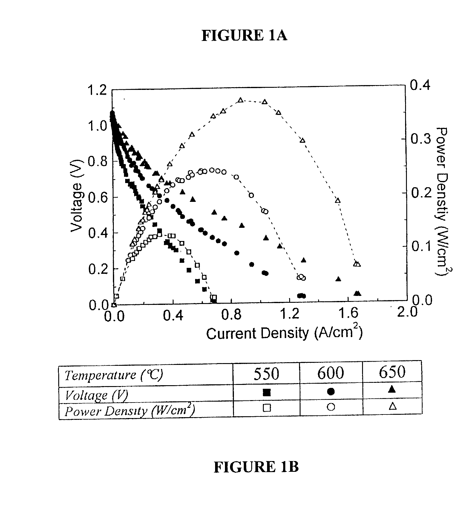
[0101] Single-cell current-voltage measurements were carried out in air and methane. Identical results were obtained for pure and humidified (containing 3% H.sub.2O) methane in the early stages of cell tests; while cell performance was stable with dry methane, after .apprxeq.2 hrs of testing in humidified methane, cell performance degraded because of oxidation of the anode Ni. FIG. 1 shows the measured current density and power density vs. voltage. The open-circuit voltage (OCV) was 1.06V. The current density vs. voltage curves were non-ohmic indicating a substantial electrode overpotential. Based on prior studies of these cells operated on hydrogen fuel, the current densities were limited primarily by cathode, overpotential. Current densities increased with increasing temperature, such that maximum power density increased from 250 mW / cm.sup.2 at 600.degree. C. to 370 mW / cm.sup.2 at 650.degree. C.

example 2

[0102] By way of comparison, the results of Example 1 were similar to those obtained for cells operated with humidified hydrogen fuel, except that the power densities were .apprxeq.20% greater. Visual observation, energy dispersive x-ray (EDX), and scanning electron microscopy (SEM) observations of the anodes, carried out after the call tests, showed no evidence of carbon deposition after .apprxeq.100 hrs of operation.

example 3

[0103] Successful cell operation on dry methane (Example 1) indicated that direct electrochemical oxidation, CH.sub.4+2O.sub.2=2H.sub.2O+CO.sub.2 .DELTA.G.degree.(600.degree. C.)=-800 kJ / mol (3) was the primary anode reaction mechanism. The OCV values measured in Example 1, .apprxeq.1.06V, were typically very close to the values measured for these cells operated with 97% H.sub.2+3% H.sub.2O fuel. This is reasonable given that the .DELTA.G.degree.(600.degree. C.) values are similar for eqn. 3 and hydrogen oxidation. The exact Nernst potential for eqn. 3 cannot be calculated since the, H.sub.2O and CO.sub.2 partial pressures are not known, but the measured OCV.sub.s suggest reasonable values, <0.18 atm for H.sub.2O and <0.09 atm. CO.sub.2.

[0104] While eqn. 3 shows electrochemical oxidation of methane, it should be noted that the present invention contemplates the possibility of other reaction mechanisms for the desired oxidation products. For instance, various intermediate reactions a...


PUM


Abstract

A method of using a hydrocarbon fuel to operate a solid oxide fuel cell, such a cell comprising one or more components which can be prepared using a centrifugal deposition technique of the type described herein.

Description

[0001] This application is a continuation-in-part of and claims priority benefit from application Ser. No. 09 / 833,209 filed on Apr. 10, 2001, which is a continuation-in-part of and claims priority from application Ser. No. 09 / 441,104 filed on Nov. 16, 1999, issued as U.S. Pat. No. 6,214,485 on Apr. 10, 2001.[0002] This invention relates generally to fuel cells and assemblies, more particularly, cells and components thereof as can be configured for use with hydrogen fuel or the direct oxidation of hydrocarbons.BACKGROUND OF INVENTION[0003] Fuel cells are promising electrical power generation technologies, with key advantages including high efficiency and low pollution. Most potential near-term applications of fuel cells require the use of hydrocarbon fuels such as methane, for which a supply infrastructure is currently available. However, fuel cells typically operate only with hydrogen as the fuel. Thus, current demonstration power plants and planned fuel-cell electric vehicles must ...

Claims


Application Information

Patent Timeline
IPC IPC(8): H01M2/18H01M4/86H01M4/90H01M4/96H01M8/00H01M8/04H01M8/10H01M8/18
CPCH01M4/8621H01M4/8828H01M4/8885H01M4/90H01M4/9033Y02E60/525H01M8/0637H01M8/1253H01M8/126Y02E60/521H01M4/92Y02E60/50Y02P70/50
Inventor BARNETT, SCOTT A.LIU, JIANG
Owner NORTHWESTERN UNIV
Why Eureka
Try Eureka