UV curable powder suitable for use as a photoresist

a curable powder and photoresist technology, applied in the field of uv curable powder suitable for use as a photoresist, can solve the problems of reducing the resolution of the pcb to be obtained, reducing the resolution of the pcb, so as to achieve the effect of better resolution

Inactive Publication Date: 2003-09-11
DSM IP ASSETS BV
View PDF7 Cites 14 Cited by
  • Summary
  • Abstract
  • Description
  • Claims
  • Application Information

AI Technical Summary

Benefits of technology

0106] Surprisingly the photoresists according to this invention are not sticky (tacky) even at high temperature, and can be used in contact with a photomask or phototool without damaging it. Room temperature cure is also possible, but usually requires higher doses of radiation. As it is well known to those skilled in the art, contact printing gives better resolution than the projection method. Direct contact without a protective cover sheet also brings advantages to the ultimate resolution achieved.
0107] Since free-radical initiators generally exhibit their maximum sensitivity in the ultraviolet range, the radiation source should furnish an effective amount of this radiation. Both point or broad radiation sources are effective. Such sources include carbon arcs, mercury-vapor arcs, electrodeless, microwave stimulated lamps, fluorescent lamps with ultraviolet radiation-emitting phosphors, argon glow lamps, pulsed Xenon lamps, electronic flash units and photographic flood lamps.

Problems solved by technology

Use of these photoresists creates a substantial waste of polyethylene and polyester films.
A limitation exists in obtaining thin layers between the carrier and protective films, which sets limitations on the resolution of the PCB to be obtained.
The polyester protective film causes light scattering, which also decreases the sharpness of the image and resolution.
One of the disadvantages of a liquid photoresist is the difficulty in obtaining reproducible and consistent thin layers by existing techniques.
Another disadvantage is the required use of very expensive application equipment.
The use of liquid photoresist also has a number of disadvantages: the liquid photoresists usually contain volatile organic solvents or diluents that need to be evaporated to form a dry (tack-free) coating on the board.
Many disadvantages can be envisioned with this process, like for example the need to employ expensive recovery systems, acquire environmental permitting, and secure proper protection from fire hazards.
It may still contain traces of solvents and is easily damaged by stacking, transport systems and handling between processing steps.
However, in this latter case, the photopolymerizable liquid diluents have the disadvantage that it is virtually impossible to obtain a dry (tack-free) coating.
Cure of a photoresist in the liquid state through a photomask without protective coatings means that non-contact printing should be used, which will result in lower resolution than contact printing.
Furthermore it is very difficult to develop these powder compositions, using water-alkaline solutions.
Such formulations require extended development times. Longer development times often lead to degradation of the cured part of the resist.
Furthermore disadvantages of these methods of application of the powder to the copper containing plate are the relatively low speed of the powder application and the limitation in the minimum film thickness and film thickness uniformity that can be obtained

Method used


Image

  • UV curable powder suitable for use as a photoresist

Examples


example i

[0121] Preparation of a Powder Photoresist 10 kg of powder photoresist was prepared by premixing all the components presented in Table 2 by the Wt. % ratio in a "Diosna" V-30 batch mixer.

2 TABLE 2 Components Wt. % CarbosetGA 1160 13.3 CAP-UV-100 8.2 Joncryl 694 45.2 SR-368 4.8 SR-349 4.5 SR-295 15.4 Irgacure 907 2.0 ITX 0.7 Quantacure EPD 2.2 Irgacure 819 1.2 Irgacure 2959 1.3 Benzotriazol 0.3 BYK-356 0.4 Victoria pure Blue BO 0.1 Irganox 1010 0.4

[0122] After mixing, the mixture was extruded on a Prizm Extruder at 168.degree. C. at 200 RPM. A clear extrudate was obtained without visible non-homogeneous inclusions. After cooling the extrudate, the extrudate was milled first in a hammer mill to a particle size <3 mm and then fed into a fluidized bed mill (Condux CFS8), having a nozzle diameter of 4 mm. The material was milled with 5 bar air overpressure at 1900 rpm of the classifier wheel incorporated in the mill obtaining a powder photoresist with a median particle size of 24 .mu.m a...

example ii

[0124] Preparation of a Carrier

[0125] 998 parts by weight Cu--Zn-ferrite powder, having a median particle size of 81 .mu.m and a ratio X.sub.75,3 / X.sub.25,3 of 1.32 (both measured with the laser granulometer Cilas HR 850), were dry coated with two parts by weight polyvinylidenedifluoride (Kynar 301F.TM.) by mixing both materials in a Lodige mixer and coating the polymer on the surface of the ferrite in a rotary kiln at 200.degree. C. under Nitrogen to obtain a carrier with a median size of 80 .mu.m, a ratio X.sub.75,3 / X.sub.25,3 of 1.32, a resistance of 1.1*10.sup.10 Ohm at a potential of 10V and a break-through voltage above 1,000V (both measured in a c-meter of Epping GmbH).

example iii

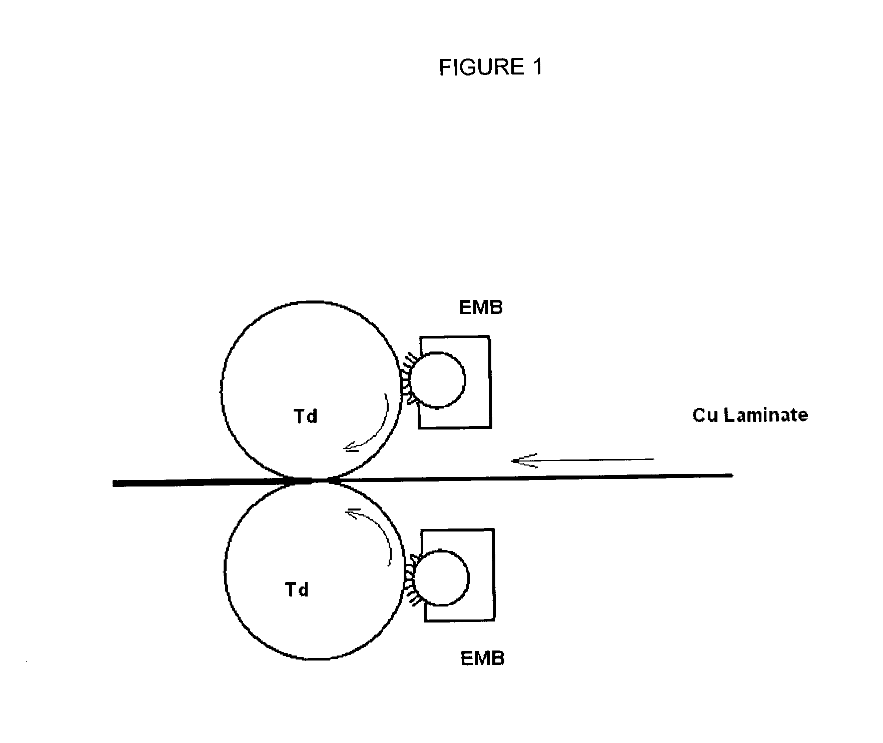
[0126] Preparation of EMB-Developer for Flexible Cu Laminated Substrate.

[0127] 20% by weight of the powder composition made according to Example 1 and 80% by weight of the carrier according to Example II were brought into the EMB-developer station OCE-2240, which is build in a prototype EMB-machine.

[0128] Total filling was 8 kg. The powder photoresist and the carrier were mixed for one minute in order to obtain an EMB-developer. The charging of the EMB-developer was measured in a Q / m of Epping GmbH, showing charge value of 15 .mu.Coulomb / g.


PUM

PropertyMeasurementUnit
Tgaaaaaaaaaa
Tgaaaaaaaaaa
Tgaaaaaaaaaa

Abstract

The invention relates to a radiation curable powder photoresist composition comprising the components A a polymer, B a reactive compound having unsaturated groups and C a free radical photoinitiator, wherein the powder photoresist composition is soluble in a developer and wherein the powder photoresist composition has a Tg between 40 and 120° C.

Description

[0001] The present application claims the benefit of U.S. provisional application No. 60 / 330,806 (filed Oct. 31, 2001) and No. 60 / 355,794 (filed Feb. 12, 2002). Both provisional applications are hereby incorporated in their entirety by reference.[0002] The invention relates to a UV curable powder composition suitable as for example a photoresist composition (or photoresist), photodielectric or photo-definable buried passive material, to a method of application of the powder composition to a substrate and to substrates having a layer of UV-cured powder composition like for examples printed circuit boards. More particularly, this invention relates to a UV curable powder suitable for use as an image photoresist that may comprise high Tg polymeric binders, a reactive component or mixture of reactive components having unsaturated groups and photoinitiators. The powder may be applied to a substrate by an electromagnetic brush. The new UV curable powder applied by electromagnetic brush is ...

Claims


Application Information

Patent Timeline
Patent Type & Authority Applications(United States)
IPC IPC(8): G03F7/004G03F7/027G03F7/031G03F7/032G03F7/033G03F7/035G03F7/16G03F7/32H05K3/00H05K3/06
CPCG03F7/027G03F7/031G03F7/032G03F7/033G03F7/035H05K2203/1355G03F7/32H05K3/0079H05K3/064H05K2203/105G03F7/164
Inventor MISEV, TOSKO A.BRATSLAVSKY, SVETLANA A.VAN DE BERG JETHS, ROBERTBINDA, PAUL H.SCHMID, STEVEN R.
Owner DSM IP ASSETS BV
Why Eureka
Try Eureka