Method for charging a structure comprising an insulating body

a charging method and structure technology, applied in the field of charging a structure comprising an insulating body, can solve the problems of difficult control of the nature difficult application of the corona effect, and difficult control of the deposited charge and its distribution

Inactive Publication Date: 2003-10-02
COMMISSARIAT A LENERGIE ATOMIQUE ET AUX ENERGIES ALTERNATIVES
View PDF5 Cites 13 Cited by
  • Summary
  • Abstract
  • Description
  • Claims
  • Application Information

AI Technical Summary

Problems solved by technology

However, use of the corona effect is difficult to the extent that it uses a large number of gas ionization and ion deposition processes on the surface of the sample.
The nature of the deposited charge and its distribution is then difficult to control.
Furthermore, since the experiment frequently takes place in an ambient atmosphere, a recombination of surface charges with ions in air contributes to the decay, which complicates application of the experiment.
This thickness is difficult to control.
Consequently, this technique cannot be applied for studying thin layers.
Finally, an excessively high secondary electronic emission can create complex distributions between positive and negative charges.
The use of this...

Method used


Image

  • Method for charging a structure comprising an insulating body
  • Method for charging a structure comprising an insulating body
  • Method for charging a structure comprising an insulating body

Examples


example 1

Charging a Polyethylene Film and Calculating the Static Dielectric Constant and the Injection Field

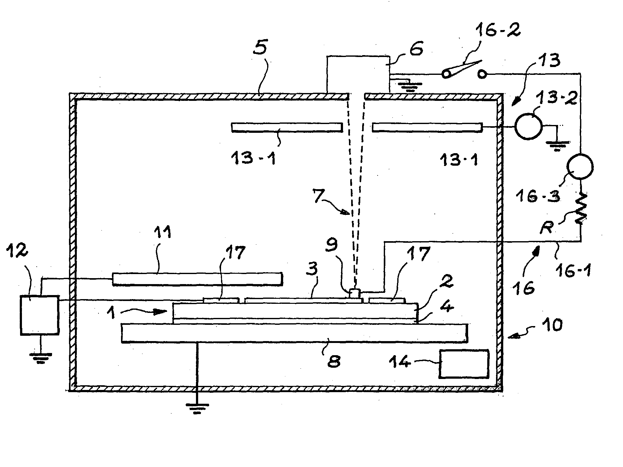
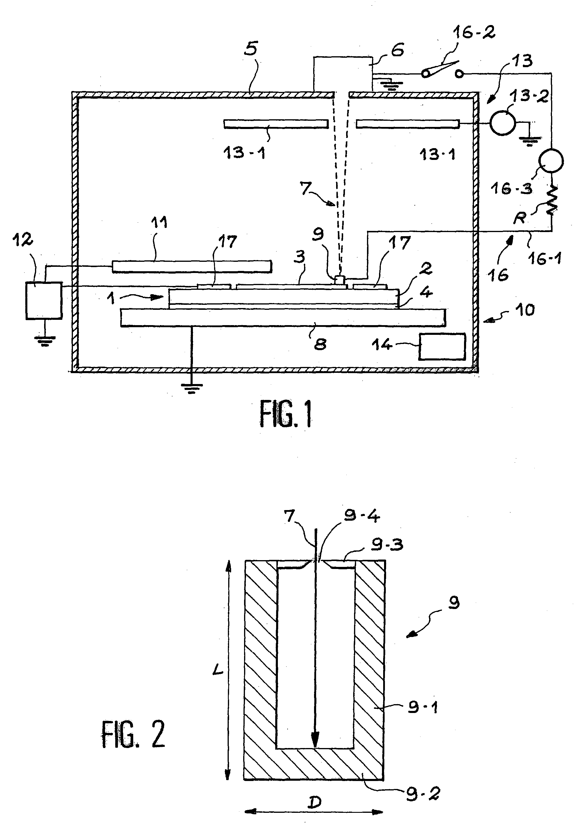
[0074] A 46 micrometer thick polyethylene film was obtained using pellets put in a mould and hot pressed using an 80 mm diameter conducting plate that will be used as a second electrode. This plate is then put into contact with the sample holder. A Kapton sheet was placed at the bottom of the mould to facilitate separation of the film. The other face of the film was metallized with gold over a 50-millimeter diameter to form the first electrode that will support the Faraday cage. No guard electrode was made. The film thus metallized was placed in a chamber similar to that shown in FIG. 1. The electrons were deposited in 5 nC packets.

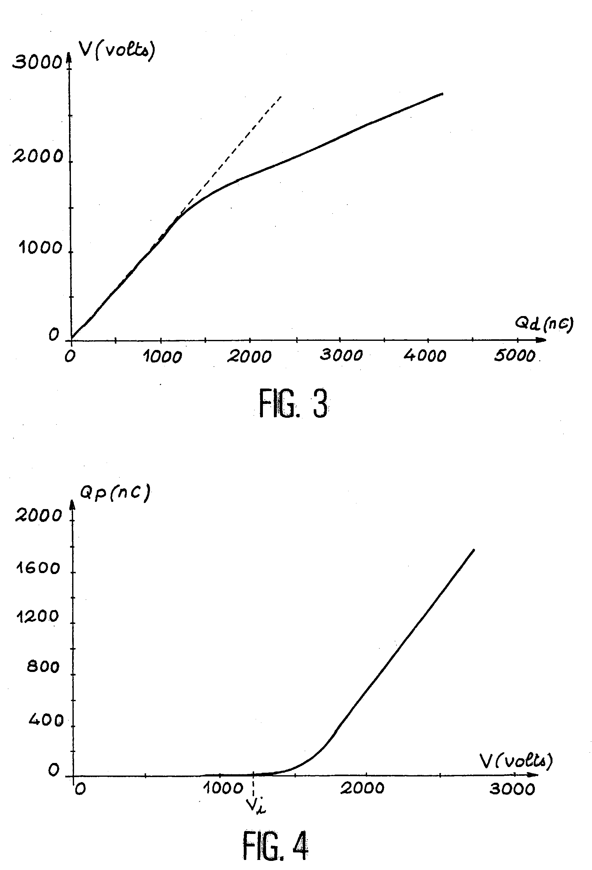
[0075] FIG. 3 shows the potential variation V as a function of the quantity of charges Q.sub.d deposited on the first electrode.

[0076] In order to interpret this measurement, it is assumed that the surface of the first electrode is very much greater than the...

example 2

Measurement of the Potential Decay and Calculation of the Mobility of Charges and the Conductivity as a Function of the Field

[0085] We will use a 114-micrometer thick polyethylene film obtained according to the procedure described in example 1. A 1 microCoulomb electron charge was deposited on the first electrode as in example 1. At the end of the injection phase, the charge quantity remaining on the surface of the electrode and the charge quantity lost by conduction during injection, are known perfectly. The potential decay of the first electrode as a function of time is then measured.

[0086] FIG. 5 shows the variation of the potential V as a function of the decay time t. The decay rate dV / dt is usually measured as a function of time, particularly because it can be used to determine the transit time T.sub.t of the injected charge from the first electrode to the second electrode. dV / dt is considered to be constant during the transit, as can be seen in FIG. 6. Beyond T.sub.t, the deca...

example 3

Measurement of the Potential Return

[0100] FIG. 8 shows a representation of the potential return measured on a 120-micrometer polyethylene film obtained according to the process described in example 1. The potential of the structure made using this film was initially raised to 2084 volts using the charging process described in example 1. After a given potential decay time during which the potential of the structure changed to 1565 volts (see example 2), the structure was short circuited so as to eliminate the potential of the top electrode, and then the potential probe was used to measure the new variation of this potential as a function of time.

[0101] Details of the theoretical approach for this potential return phenomenon are described in document {12}. Assuming that the charges are distributed in a plane at an initial depth .lambda., it is proposed to calculate the charge density q and the initial depth of charges .lambda. using the following formulas: 3q = V 0 + V .infin. h { 13 ...


PUM


Abstract

Process for charging a structure (1) formed from an insulating body (2) sandwiched between two electrodes (3, 4), characterized in that it comprises the following steps: A Faraday cage (9) is placed in contact with one of the electrodes (3) of the structure (1), the potential of the other electrode (4) being made equal to a reference potential. Electrons originating from a controlled electron emission device (6) are introduced into the Faraday cage (9), the electrons reaching the electrode (3) with which it is in contact in order to charge the structure (1). Application particularly for the determination of properties of insulating materials.

Description

TECHNICAL DOMAIN[0001] The present invention relates to a process for charging a structure comprising an insulating body and a charging device for such a structure. Control of conditions for charging an insulating body, in other words knowledge of the quantity of the charge and the distribution of the charges then makes it possible to study the potential decay phenomenon from when it starts, and the potential return with time after the structure has discharged. These studies then determine the electrical properties of the body such as the electronic mobility of the insulating material, its conductivity and its dielectric constant. Knowledge of these properties is essential to determine the aptitude of new insulating materials for industrial use, for example in capacitors, electrical cables, semiconductors, electronic tubes.STATE OF PRIOR ART[0002] The state of prior art is illustrated by documents [1] to [12] listed at the end of this description.[0003] For the purposes of studying ...

Claims


Application Information

Patent Timeline
IPC IPC(8): G01Q30/10G01Q30/16G01R27/26G01R31/305
CPCG01R31/305G01R27/2617
Inventor BIGARRE, JANICKHOURQUEBIE, PATRICKMATALLANA, JEROME
Owner COMMISSARIAT A LENERGIE ATOMIQUE ET AUX ENERGIES ALTERNATIVES
Why Eureka
Try Eureka